
Heartwatch
The ticker-ticker
 Watch out
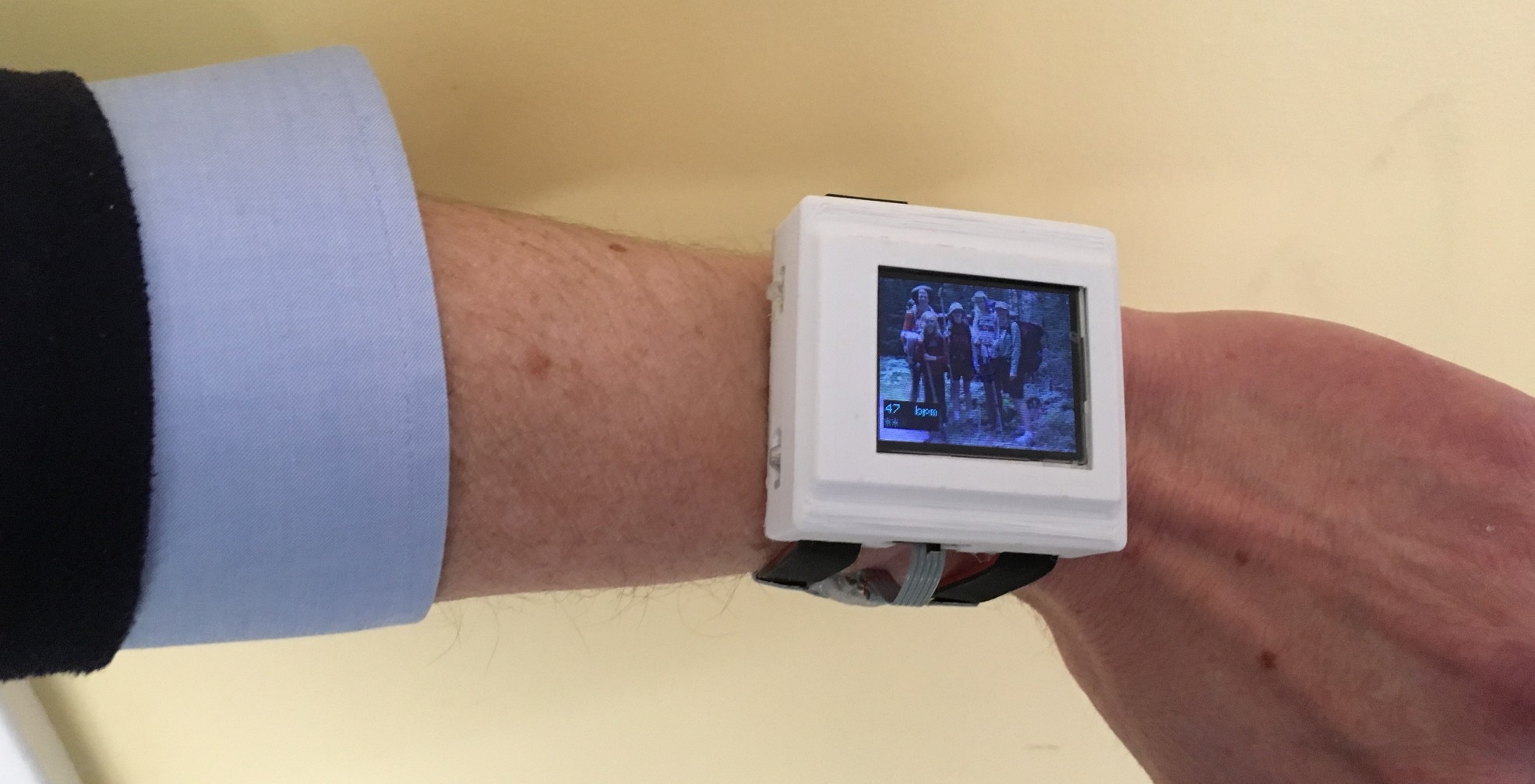
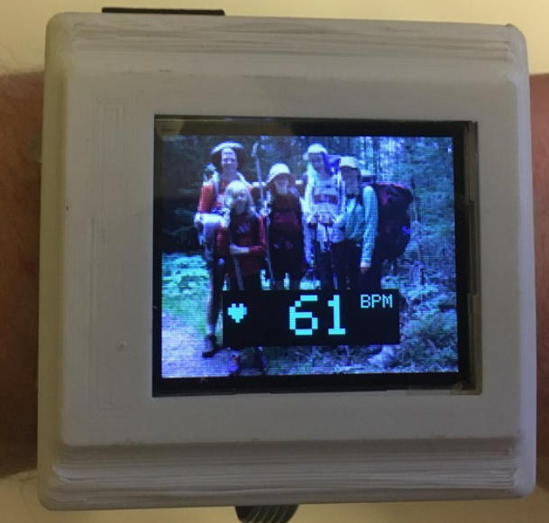
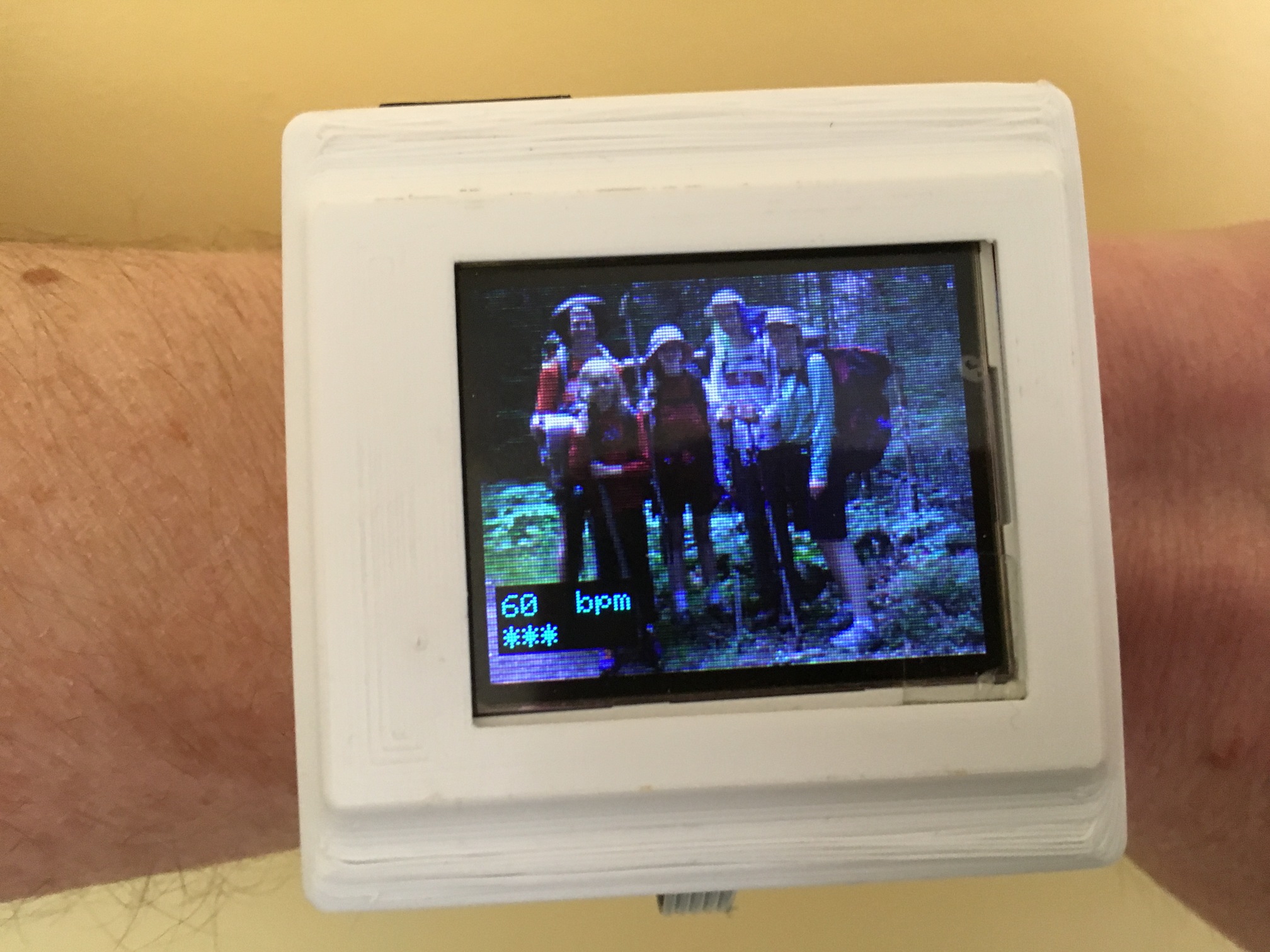 Resting heart rate of 60 bpm? Need to do a few more of these hikes
Project overview
What it is
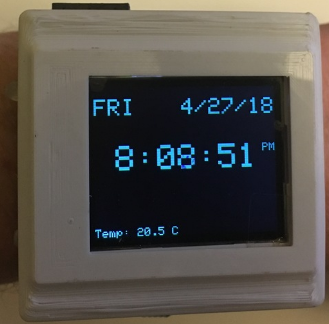
This watch will keep time accurately, measure heart rate, measure SPO2%, act as a compass, measure altitude, air pressure & temperature, measure your acceleration and angular rotation. It has a color LCD display, SD card slot, a mini-USB charging port, an ISP programming port, a serial debugging port and pushbutton interface. All of the functions are accessed by a menu-driven user interface. Oh yeah, I also tried to keep it reasonably compact.
 Would you like fries with this delicious burger?
Screenshots
Here are current screenshots of various apps - I’ll add/update as new things become available.
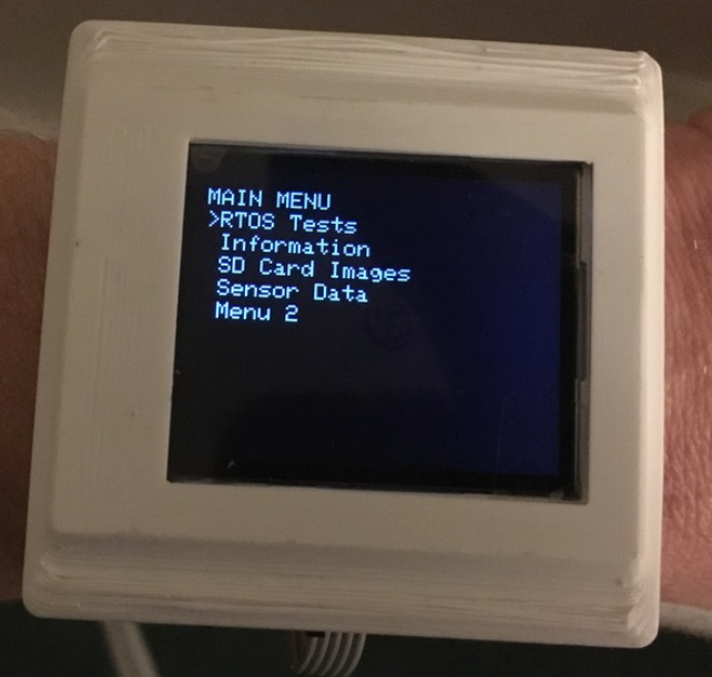
Menu & Navigation
Clock & Setting the time
Heartrate
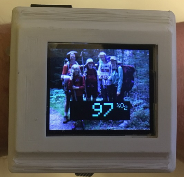
SPO2
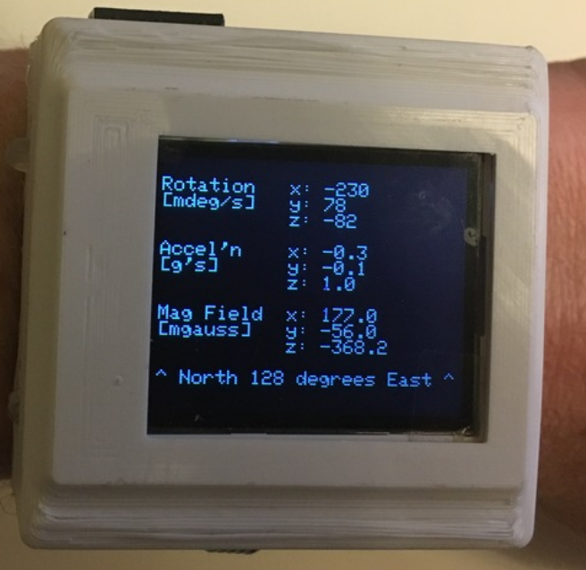
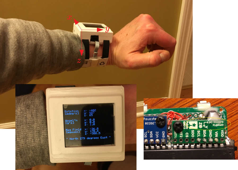
Compass, Gyro & Accelerometer
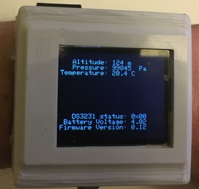
Pressure, Altitude & Temperature
What it (currently) is not
I thought about supporting Wifi or Bluetooth connectivity, but in this first version I opted against it to keep the power draw and initial complexity to a minimum. I figured getting the heart rate measurement working robustly would be enough of a challenge (it was!). So it isn’t really a bona-fide “smartwatch”. The way I look at it, its just something to put on the list for rev 2.
S.T.E.M.
So what are the interesting tech bits here?
Measuring Heartrate and SPO2 with Plethosysmography
The simple idea behind this is that light (say, from an LED) penetrates your skin and makes its way to your veins (and everywhere else within its cone of illumination). At every single interface along the way, a tiny bit gets reflected back. The path the light takes is the same from instant to instant, so the amount reflected should not change, except for one place: where the blood is flowing. That path is changing from instant to instant because your heart is pumping the blood through it. This changes the density (local amount) of the blood, which changes how much light gets absorbed at this spot, which changes how much is available to get reflected. With this simple fact, you can actually measure your heartrate, because it produces a somewhat regular reflection that changes as your heart pumps. Cool.
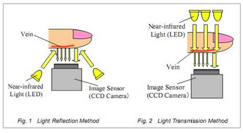 Reflecting light off of your vein can help you measure blood flow, and therefore your heartbeat
Adding one more fact: depending on the color of light you use, the amount reflected changes. This is mainly because your skin absorbs different colors of light differently. You can use this to get a bigger (or smaller) reflected signal to work with. Obviously, where you shine the light matters too. Hitting bone would not be that helpful, for example.
Adding just one more fact. Your blood also absorbs different colors of light in different amounts. However, the amount of oxygen in the blood determines just how differently. So what happens if shine two different colors (say, red at 650 nm and infrared at 850 nm - foreshadowing), look at their reflections, and watch how they change? Not only would we be able to measure the heartbeat from each color individually, but we could also measure how much oxygen is bound up by hemoglobin in the blood. All of this just by looking at the difference in reflected amount between the two colors. This is called pulse oximetry. Very cool.
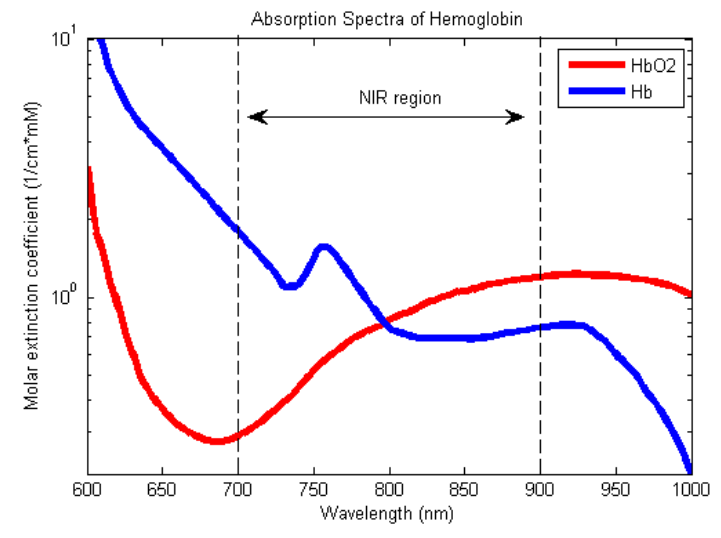 Oxygenated and non-oxygenated hemoglobin absorb light in very different ways
The actual measurement we are making is something called SpO2, the % of hemoglobin that is saturated (that’s where the S comes from) with oxygen (O2), using pulse oxymetry (p). You can also make a direct arterial (a) measurement & get SaO2. Neither of these measures the other component of oxygen (the free oxygen that is not attached to hemoglobin - PaO2). There is a curve that will give you this second number knowing the SpO2. You can add the two of them, and do a bit more math to get CaO2, which tells you the total concentration of oxygen. For now, we’ll measure the SpO2 and leave it at that.
Really what I want to know is what my pulse ox #’s look like before and after exercising.
Getting it to actually work with minimal “devil”opment
The devil, of course, is in the details. What colors to choose? Where to place the LED? Where to place the detector? Will the signal be big enough? What if I jiggle my arm? Will it be accurate? How fast do I need to sample? Will there be too much noise to be able to get anything interesting? I’ll talk through most of these things in the blog post. Its interesting that it all (physics of light, biology of the vascular system, sensor technology, low noise electronics, digital signal processing, software, packaging) needs to work together for a good user experience.
I will mention right away, though, that companies are making sensor devices that make several of these choices for you. For example, the MAX30102 chip I used has a red & infrared LEDs, and detectors, and electronics all built in for you. The MAX30101 (which I haven’t played with yet) adds a green LED for even more flexibility!
Placement on the arm
The second thing I’ll mention is that this whole thing would be a non-starter if the only place you can measure anything is on your finger tip. I wanted to make a watch-like thingy, not a glove. Usually I don’t get lucky with these projects (as you know by now I learn by re-doing), but it so happens the position of the sensor that produced a good signal was pretty much in line with where a watch would naturally sit on my arm. Nice.
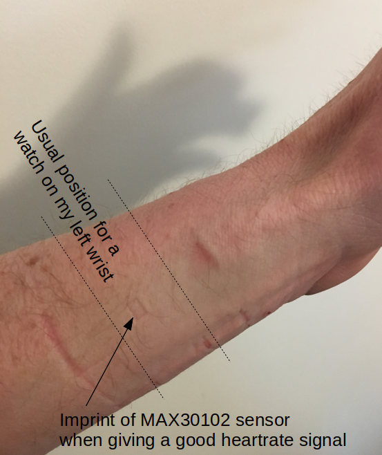 After some experimentation, this was a good place for the sensor to give a decent signal
Accelerometers, Gyros & Sensor Fusion
The other technology that has come a very long way in the last 25 yrs is “PNT”, or positioning, navigation and timing, with advances like GPS and miniaturized gyrocompasses and accelerometers. Gyro/acc sensors work by having an extremely small “proof mass” that is set into a back and forth vibration using electronic techniques. As you change either the orientation of the mass relative to gravity (by moving your smartphone around - which has these chips inside it), or if you accelerate the mass (say by running with your smart phone), the details of these vibrations change. You measure them and figure out which way things are moving. There’s a bunch of interesting math behind this.
A “macro” analogy would be watching how your back-and-forth motion on a playground swing would change if gravity suddenly started acting up instead of down, or if someone came up and started pushing you from the side instead of from behind. Studying your swinging motion on a video camera would allow you to figure out what forces were acting on you, and from where. That’s what these tiny chips do.
Hardware - Electronics
There was a ton of hardware in this project, so lets go piece by piece. I actually individually breadboarded almost every element just to convince myself this whole thing didn’t have any showstoppers.
Microcontroller choice
I went with the ATMega1284 for this project. The 40-pin version I have is a bit on the large side physically, but since I’m hand assembling it all, that doesn’t really matter. And I’m not going for style points. It has 128K Flash, 16K SRAM and a 4K EEPROM. I’ll clock it at 16MHz with an external crystal. I’m sure I’ll hit some limitations, but lets see how far we get.
Battery and charging circuit
I’m putting this up front: this is as important a decision as the microcontroller. I wanted a nice, compact 500 mAh 1-cell Li-ion battery and found a great little mini-USB charging circuit for it.
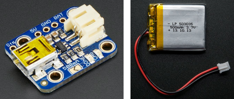 A nice compact LiPO charger and battery for this project
Sold. The main implication is that everything needs to be designed for 3.3V. And I also need to worry about power consumption, but I’ll cross that second bridge later. The charger also has a couple of LEDs on it to show charging progress - and they are bright enough to show up through my watch skin:
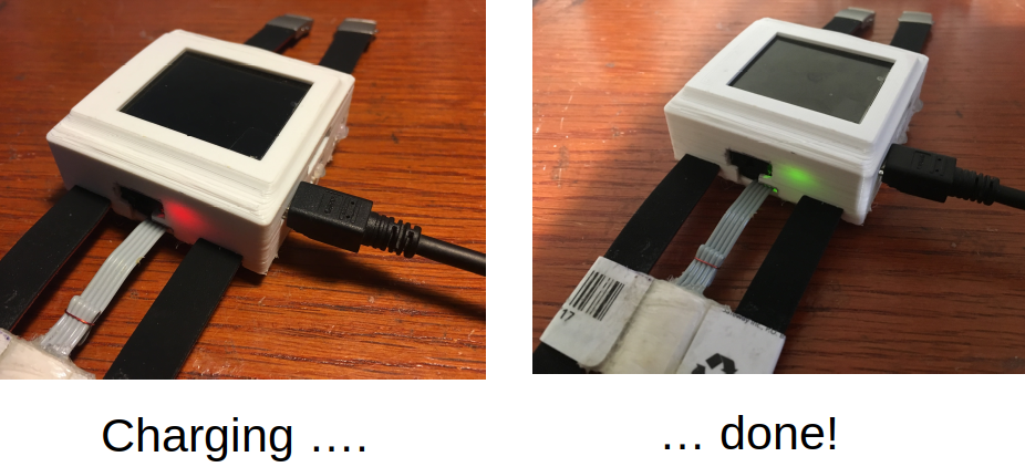 Topping it up
DS3231 Real time clock + Battery
A watch should keep time, and reasonably accurately. There are a ton of options, but I went with Maxim’s DS3231M. Its only 8-pins, doesn’t require an external crystal, and needs just one decoupling capacitor and a small battery for backup power when the main battery is off. Its got an I2C interface, and a bunch of cool functions. I made my own little header for it.
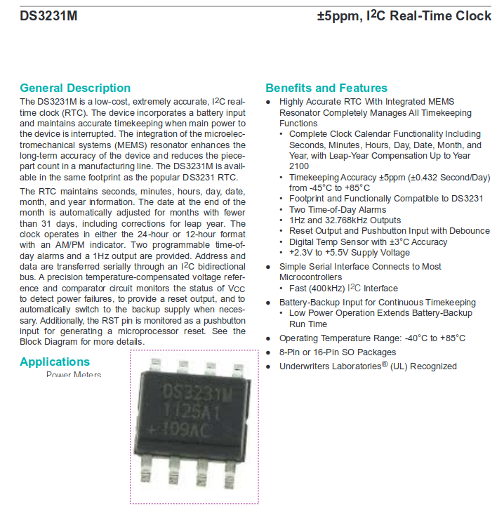 An 8-pin real time clock (RTC) that needs no crystal!
For the battery, I used a low profile 3V Li cell CR1025. I took a file, roughed up both sides and (very quickly, to minimize heating) soldered a wire to each. Then I encapsulated the whole thing in a very thin layer of hot glue to insulate it. Good to go. You can just see it tucked under the strap in the image on the right.
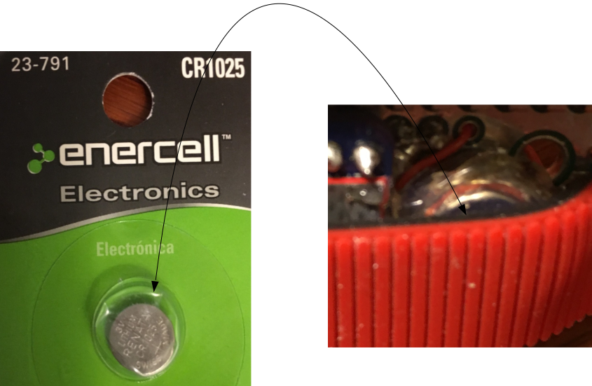 Low profile 3V battery to keep the RTC going
Of course, this failed within a week. Not sure why - I don’t think it was a bad connection. I think either the soldering was a big mistake, or the battery got shorted somewhere in the watch. Because when I pulled it out, it was 0.8V, not the 3.2 that went in. So I re-did it with a DIY battery holder:
 Plus is actually minus … plus or minus
which I also eventually covered in hot glue. I’ll do some experiments on the clock stability over time, but I don’t have any data yet.
L3GD20 Accelerometer
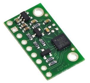 Measures acceleration
You can see x, y and z printed on the little pcb as an easy reference. The initial output looks like this:
 The gravity of the situation
Good. Without anything moving, the 1.0 beside the z direction means gravity is pointing down, which it actually is. If you want to do everything relative to gravity, you’d have to subtract 1.0 g’s (or 9.8 m/s^2) from it.
LSM303 Gyro And Compass
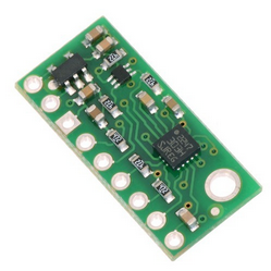 Measures rotational rate and heading relative to magnetic north
The quick check on accuracy was to see if North was correct - it was roughly where I thought, pointing to the woods across the street. Here it is compared to a hand compass:
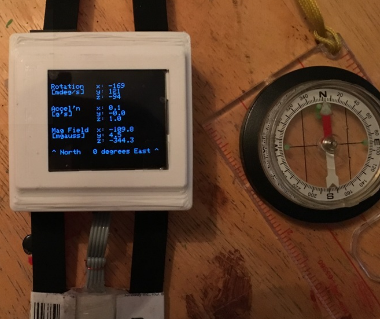 North
North
BMP085 Altitude, Pressure and Temperature Sensor
I am pretty interested in seeing how much “up and down” I do during a bike ride or a run, and also generally when out for hikes. The BMP080 pressure sensor board will be able to measure altitude, pressure and temperature accurately enough to log some of these things. It uses I2C like many of the others and is compact.
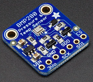 Jack of all trades
So how much “vacuum” can you get with a vacuum?
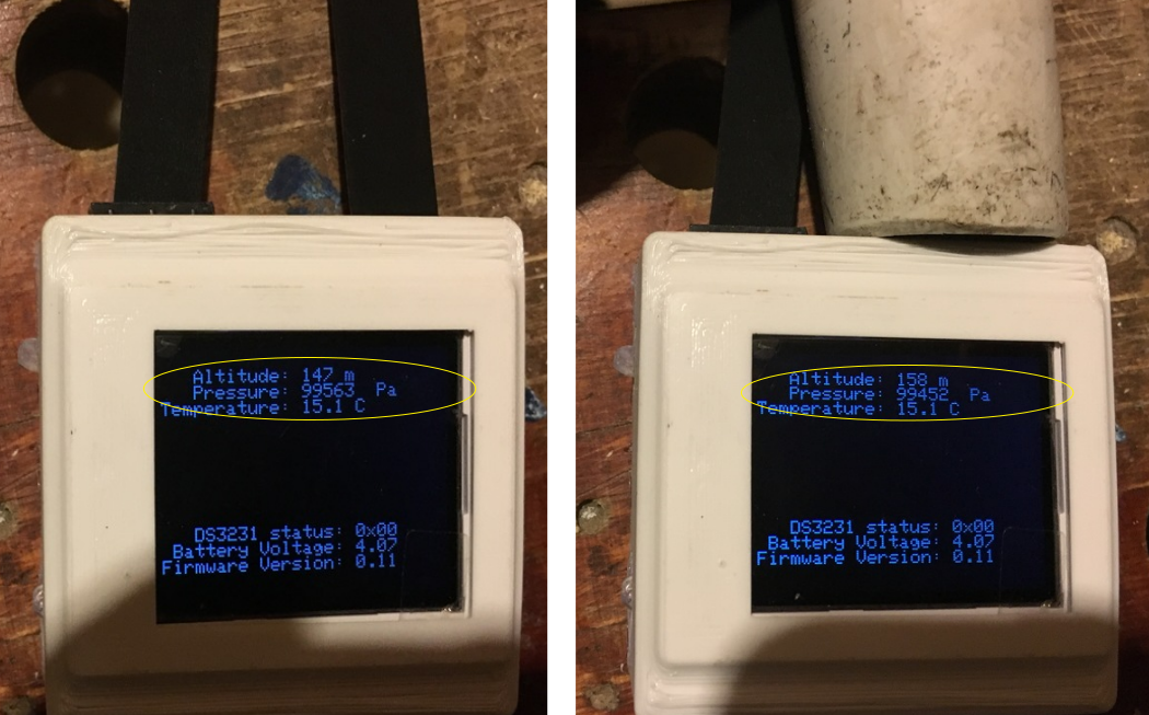 Conclusion: placing a vacuum close to a DIY smartwatch changes its altitude. ;)
MAX30102 and MAX301XX LED and photodiode
I already mentioned this guy in the intro.
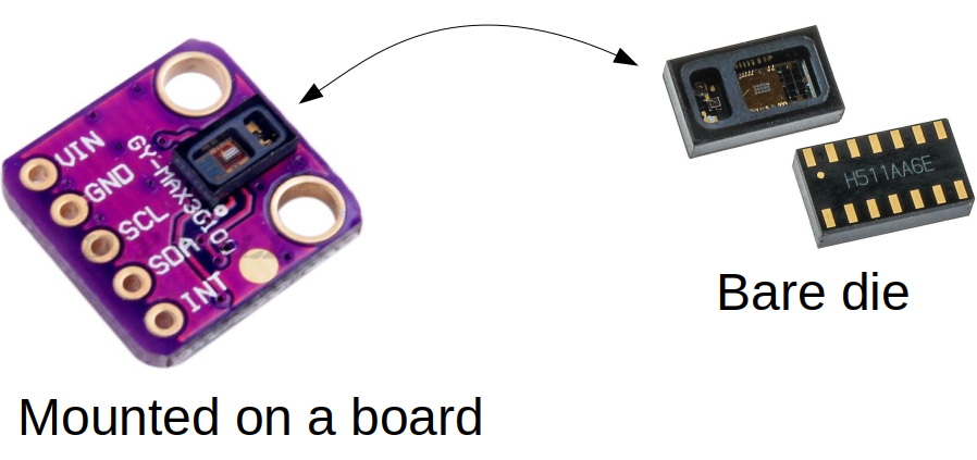 This tiny device does all the heavy lifting
ST7735 color LCD and SD card
I went for a color LCD, which came bundled with a micro SD card slot.
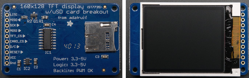 A great two-for-one
Other Connectors
The SPI header can be used for in-system programming, and the serial port is used for debugging & data logging:
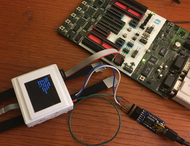 Getting stuff done
Circuit diagram & component choices
Here is a circuit diagram
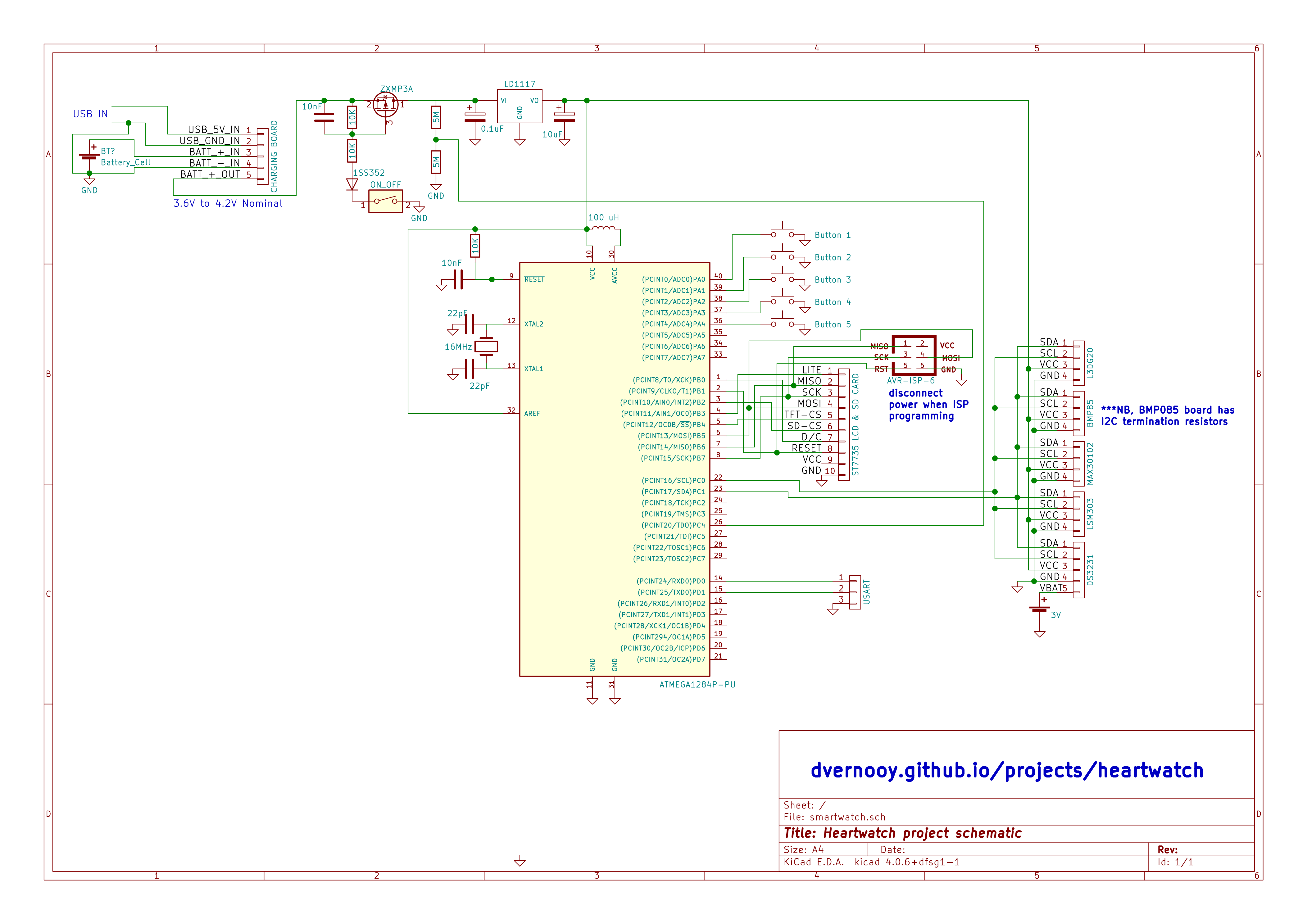 Circuit diagram for the heartwatch
I haven’t shown the individual connections for each of the sensor devices as I got them already mounted on daughter boards and access them via an i2c/twi interface using SDL and SCA. That other detail is obviously important to make this thing work, and especially if you wanted to get rid of those daughter boards and really slim this thing down. Note that the pullups for the i2c lines are essential, and not shown here since they are populated already on a couple of the daughter boards.
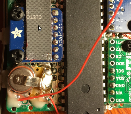
Circuit build, assembly & component mounting
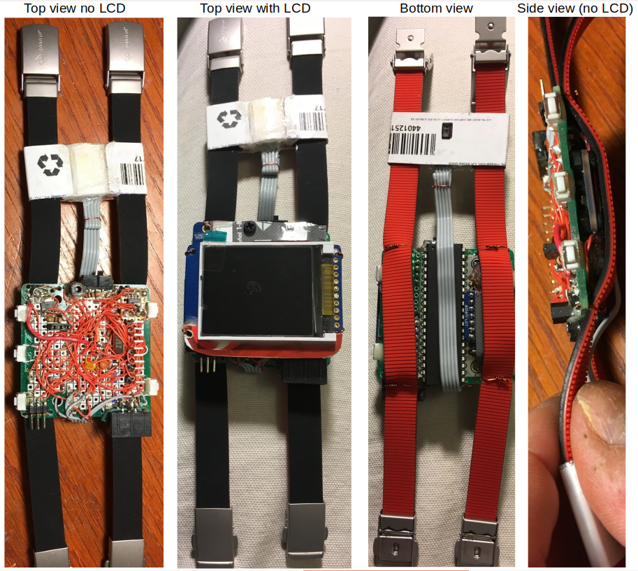 The full watch prior to assembly into its 3D-printed skin
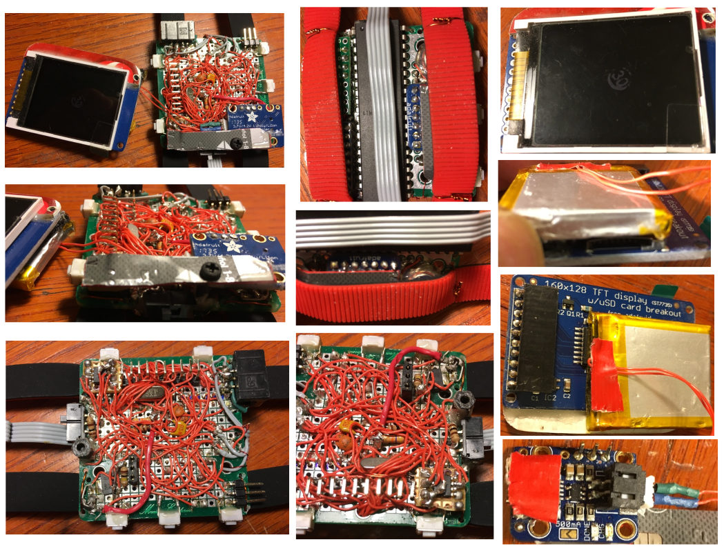 A gallery of various components and steps in the assembly
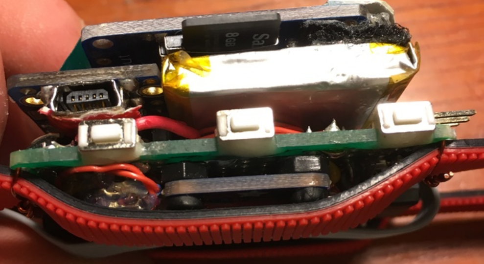
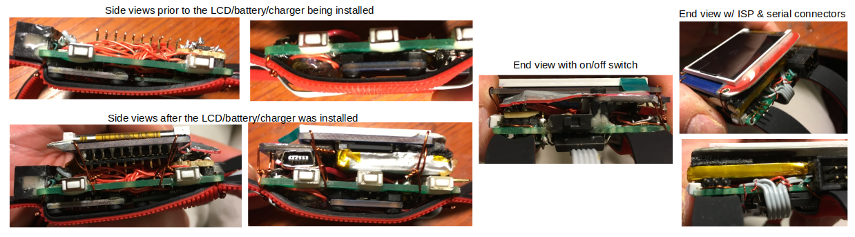 Trying to keep it reasonably thin
Hardware - watch skin and straps
Strap strategy - ROAD iD
I never really have a solid plan going into these things. Maybe it shows in the final results. Anyways, after mounting up all the parts, I needed to make this thing look a bit more real with a watch band. I didn’t want the band to be skin-irritating and it needed to somehow secure to the board and hold the whole thing in place. I went for a double: two skinny bands working together vs. one thicker one. Might look a bit goofy, not sure.
After a bit of research, I found out that ROAD iD sells replacement parts for their ID bracelets. Silicone straps and a simple metal clasp system. Simple, low cost and modifiable to my needs. Perfect.
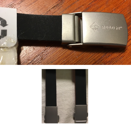 Two is better than one
They also sell a thicker one that I might try later as a single strap.
Mounting the heart rate sensor
A side benefit of the two-strap system is that now I had a decent way to hold the heart rate monitor board in the correct place on my wrist. My process was this:
- Take an old credit card and cut a roughly 3” by 1” strip
- Heat a soldering iron up and melt the plastic very briefly and then bend it before it cools. When it cools, it will harden nicely in that formed shape. Takes a tiny bit of practice.
- Using this technique, form a shape to hold the board and straps, with just the LED sensor chip poking through.
Definitely good enough for now. I build it “tight enough” to not slip in the silicone straps, but loose enough so that its position could be adjusted as needed.
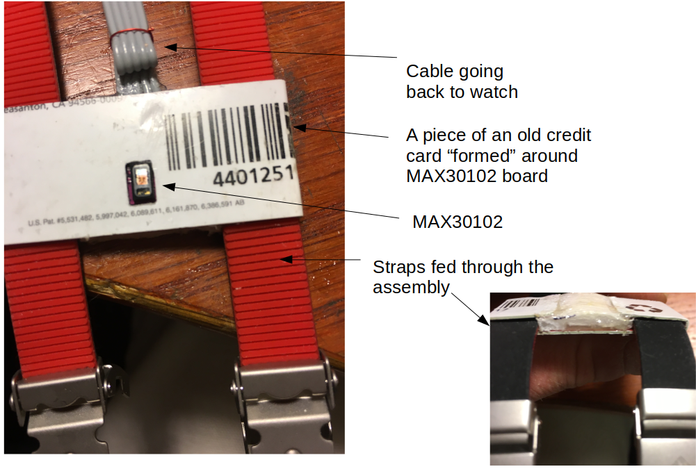 A sensible holder
Case design & 3D printing
So now that I had a roughly functioning watch, I wanted something to give it a bit more protection. I thought about using Sugru (too finicky for what I wanted) or making some Oogoo (likely not skin friendly unless I bought some aluminum-cure silicone) to form the watch protective skin. Then the kids had a week off of school and looked bored. And they each have their favorite CAD software. And their friend Rohan has a hobby 3D printer. So we whipped up a little box one morning and had it printed in polylactic acid (PLA) thermoplastic by that evening. I did a bunch of rough measurements and estimating, we had a contest to see which software was easier to use (Ian’s Fusion360 was the winner), and then went for it.
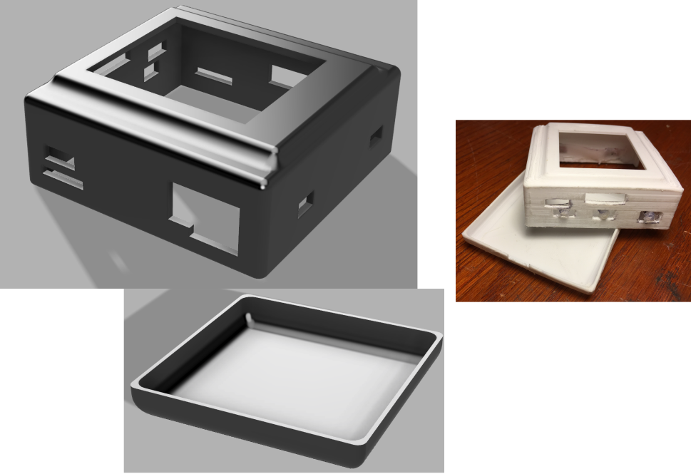 Personal Fabrication: From CAD to doo-dad in 3 hrs. Neil Gershenfeld, eat your heart out
Rohan’s the man: here is the printing in action, courtesy of his “Octoprint” setup.
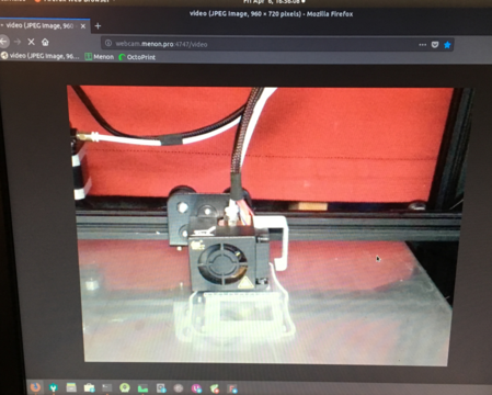 3D printing the case
It crashed with one layer to go. That’s fine, I’ll take it. And with a couple of jeweller’s files and an hour of tweaking, it was ready for assembly.
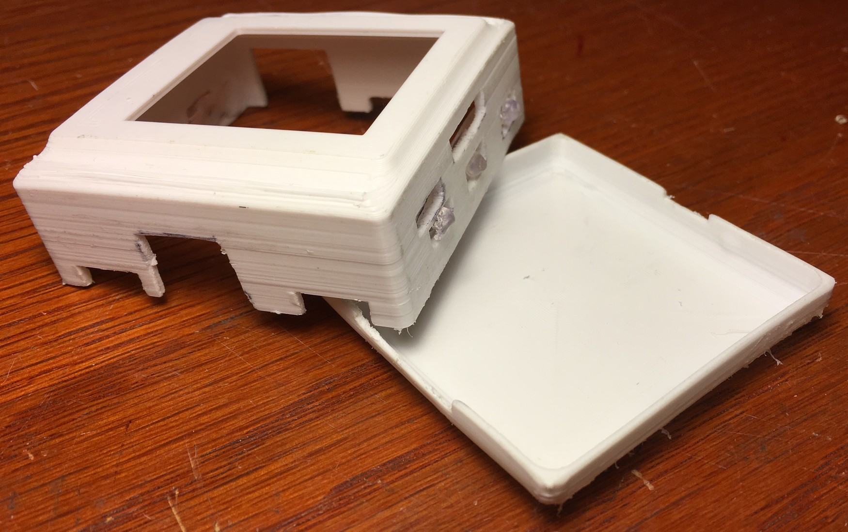 Case (almost) closed
The whole thing went together rather well. Measure once, cut twice.
Case to arm
I did end up adding some contouring to shape it more to my arm.
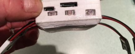 Matching my delicate contours
The current case sidewall thickness is only about 1.5 mm, so hard to do too much “after the fact” shaping right now. Add this to my list of tweaks for a rev 2.0 case.
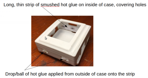
Pushbuttons - silicone & hot glue
So (almost) everything was cool about the case. Except it is hard to reach the SD card (either long fingernails or a paperclip). And then what to do about the pushbutton switches? They’re recessed & also hard to reach. Hmmmm.
Lets skip the experiments on this one.
Here’s what actually worked. Go buy some Reynolds Parchment paper. Take a hot glue gun, run a line of hot glue on it and press it really flat with another piece of parchment paper. Then release it from the paper (it won’t stick), and trim it to fit between the buttons and the 3D printed case, on the inside of the case. Hot-glue tack it there. Then from the outside, on top of this thin hot-glue skin, melt a small ball of hot glue onto it. Works awesome, and has a really nice feel to it when actuating the pushbuttons.
Here’s a close-up of what I’m talking about, and the finished result:
 Cute as a button
And because I’m so proud of this, a little video of the pushbutton “action”:
For the SD card, just keep a paperclip handy.
Software
This project is one of the more ambitious ones on the software side. I wanted full functionality, a good user experience and reasonable battery life - along with the ability to add new “apps” as I dreamed them up. The entire codebase, along with some of the spreadsheets and Matlab scripts are posted at my github repository.
Heartrate algorithm
So lets start the software discussion with the heartrate algorithm. There are 4 steps:
-
Step 1: Get a strong base signal to work with
-
Step 2: From the signal, detect whether we think a valid heartbeat just happened
-
Step 3: From the heartbeat, calculate the current heartrate
-
Go back to step 1, and make sure it’s all done fast enough
Lets start with Step 1.
Setting up the sensor
A little math says that we’ll between 30 BPM and 180 BPM (which is a maximum fundamental frequency of about 3 Hz), so the minimum inter-beat spacing will be > 300 ms. Nyquist says our absolute minimum sampling rate needs to be 2X that, or 6 Hz, for a sample time of 160 ms. Since I don’t know any better yet, I’d add a safety factor of 5 to 10, so we’ll shoot for a sampling time of 20 - 30 ms. Note that a 20 ms sampling time, for example, corresponds to a 50Hz sampling frequency.
The MAX30102 sensor allows for setting LED power levels, a number of sample averages, the number of LEDs, the sample rate, the pulse width and the range of the ADC. All of this is done in MAX30105.c.The MAX30105 and MAX30102 sensors are very similar in their register layout and share essentially identical firmware.
void MAX30105_setup(uint8_t powerLevel, uint8_t sampleAverage, uint8_t ledMode, int sampleRate, int pulseWidth, int adcRange)
Here are the settings I used when calling this function (after studying the datasheet):
MAX30105_setup(0x3F, 8, 2, 400, 411, 4096);
In particular, the sampling rate was 400 samples per second, with an 8-sample average, meaning 50 averaged samples per second … which is exactly 20 ms per sample.
DC removal
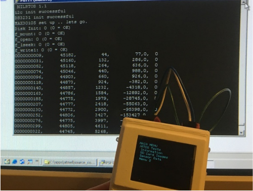
The raw signal we’re working with looks like this:
 Raw sensor signal over the I2C bus
The first step is to remove the DC. I first tried a simple DC removal filter
\[\begin{align*} y(n) =x(n) - x(n-1) + Ry(n-1) \end{align*}\]where R is a parameter that is ~ 0.8 to 0.95. For a number of reasons didn’t like the performance. More about that in a minute.
So I did my homework on this one and came across an idea for a filter that I really liked. The basic idea is to take a moving average and subtract it from a delayed version of the input:
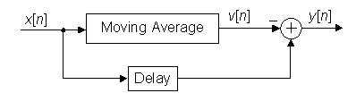 Basic idea for a digital DC blocker
The actual implementation is a bit more complex if you want it to be done quickly with integer power-of-2 math:
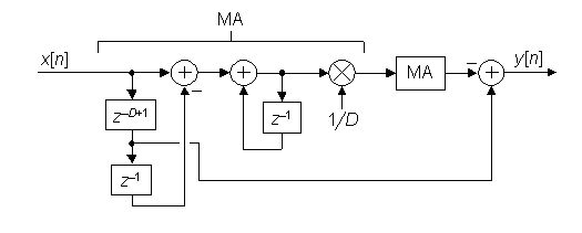 A digital DC blocking filter that performs very well
The choice of how much to average has tradeoffs - not too long that its sluggish and not too short that you aren’t really getting a good estimate of the average. I thought averaging over close to one beat (0.5 to 1s) made sense, so at a sample rate of 20 ms, this was 32 samples (closest power of 2). Something to play with later would be to make this dependent on current heartrate.
I rolled my own code to implement it, after first playing with an excel implementation to look at the behaviour. Here’s what the average estimate looks like:
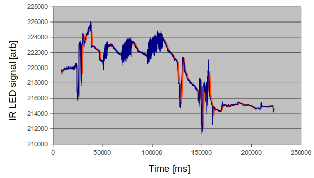 DC average (in red) follows the heartbeat signal
And here is a close-in showing how it handles largish changes in DC level. You can see that it ignores “really fast” changes that happen faster than ~ 1000 ms, but tracks the others. That’s what we want.
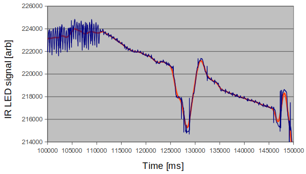 Response time of the DC average is about 600 ms
Note for that second plot I offset the average by 32 counts (approx. 600 ms) to show it right on top of the signal & eliminate the group delay of the DC block filter. The code does that naturally for us.
for (i = 0 ; i < 32 ; i++) {
  HR_state->abuf_DC[HR_state->offset_DC] += HR_state->xbuf_DC[i];
}
HR_state->abuf_DC[HR_state->offset_DC] = (HR_state->abuf_DC[HR_state->offset_DC])>>5;

for (i = 0 ; i < 32 ; i++) {
*avg_estimate += HR_state->abuf_DC[i];
}
*avg_estimate = *avg_estimate>>5;
output_buffer[0] = (*avg_estimate - HR_state->xbuf_DC[(HR_state->offset_DC+1)%4])<<2;
It rocked. I’ve posted the excel in the repo.
Filter design - rev 1
With the DC gone, the next step was to low pass filter the resulting DC-stripped signal. The transfer function of a simple digital low pass filter is:
\[\begin{align*} y(n) =y(n-1) + \alpha (x(n) - y(n-1)) \end{align*}\]which can be implemented really easily. In fact, I thought I would be clever and combine this with my first attempt at a DC removal filter above, and do both in one step. This combination has the following transfer function
\[\begin{align*} H(z) = \frac{\alpha}{1-(1-\alpha)z^{-1}}\frac{1-z^{-1}}{1-Rz^{-1}} \end{align*}\]And from that you can get the difference equation. I tried it, but didn’t like the signal quality coming out. So its back to the DC removal filter I like, and time to search for a better low pass filter.
Filter design - rev 2, analysis and synthesis
The (semi)pro way to go about this is to design an actual digital filter. Time for Oppenheim and Schaeffer. Or Google. The latter was the path of least resistance, so I went digging, and (lo and behold) buried in the Adafruit git repo for MAX3010x for “heartrate.c” was a finite impulse response (FIR) filter with the following coefficients:
static const uint16_t FIRCoeffs[12] = {172, 321, 579, 927, 1360, 1858, 2390, 2916, 3391, 3768, 4012, 4096};
Hmmm, wonder what it would do “as is” at, say, a 20 ms sample rate. Here’s the Matlab/octave script to find out with filter analysis
function FIR_test;
b = [172 321 579 927 1360 1858 2390 2916 3391 3768 4012 4096];
b = [b b(11:-1:1)];
a = 1;
fs = 50; %20 ms/sample = 50 samples/sec
[h,w]=freqz(b, a, 500, fs);
h = h./32768;
plot(w,20*log10(abs(h)));
xlabel('Normalized Frequency (\times\pi rad/sample)');
ylabel('Magnitude (dB)');
with the following result:
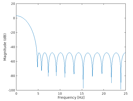 The default “heartrate.c” low pass filter, about a 1.5 Hz bandwidth
Ok, so we now know its a low pass filter, which is what we need. And since the highest heartrate I’ll ever see is ~ 180 bpm, which is 3 beats/sec (3 Hz), the 1.5 Hz 3dB low pass cutoff frequency is a little on the low side.
So, instead of hoping to get lucky with google & just using something blindly, we need to do a filter design ourselves. Turns out, there is a clever algorithm called the Remez exchange algorithm. This algorithm takes filter target “specs”, and a filter “length” and will output a design that comes close. Here is some octave code to do the filter synthesis, which only took a few minutes to get right. It sets a target passband of [0 to 0.0079] and stopband from [0.186 to 1] in normalized frequency units. These numbers were chosen to very closely reproduce the performance of the filter above:
function FIR_test;
close all;
b = [172 321 579 927 1360 1858 2390 2916 3391 3768 4012 4096];
b = [b b(11:-1:1)];
a = 1;
fs = 50; %20 ms/sample = 50 samples/sec
[h,w]=freqz(b, a, 500, fs);
h = h./32768;
plot(w,20*log10(abs(h)));
hold on;
xlabel('Normalized Frequency (\times\pi rad/sample)');
ylabel('Magnitude (dB)');

b = 46000*remez(22,[0 0.0079 0.186 1], [1 1 0 0]);
b = round(b)
[h,w]=freqz(b, a, 500, fs);
h = h./(2^15);
plot(w,20*log10(abs(h)));
You can see it both in the generated filter coefficients and the expected performance:
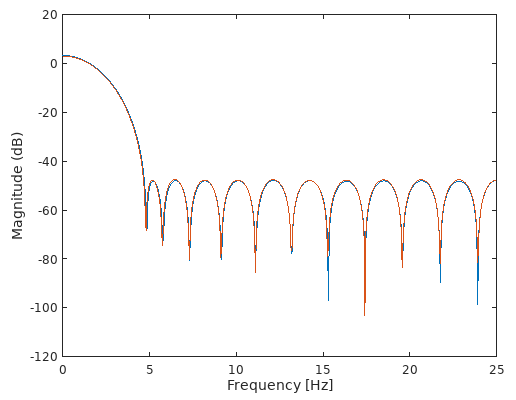 Can you tell the difference?
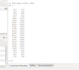 Reverse engineering
Cool. With this capability, we can now design our own filter with custom bandwidths of, say, 2, 2.5 and 3Hz bandwidth, all with N = 23 filter coefficients so the c code doesn’t need to change. Here is the relevant line in the Matlab code
%b = 46000*remez(22,[0 0.0079 0.186 1], [1 1 0 0]); %nominal 1.5Hz
%b = 46000*remez(22,[0 0.011 0.24 1], [1 1 0 0]); %2Hz
%b = 46000*remez(22,[0 0.015 0.255 1], [1 1 0 0]); %2.5Hz
%b = 46000*remez(22,[0 0.018 0.27 1], [1 1 0 0]); %3Hz
and the results:
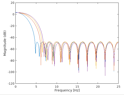 You get the idea
We can implement several of these very easily on the watch by changing that one line of code in heartrate.c and immediately assess the performance. You could also have a dynamic filter depending on your heartrate. Now that would be pro.
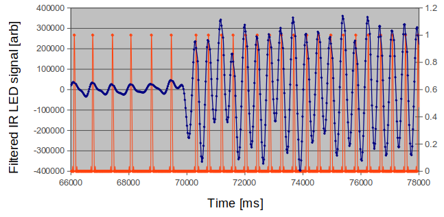
I ended up using the 2Hz filter as a good compromise between eliminating noise and keeping the detection speed high. Here is what the filtered signal looks like:
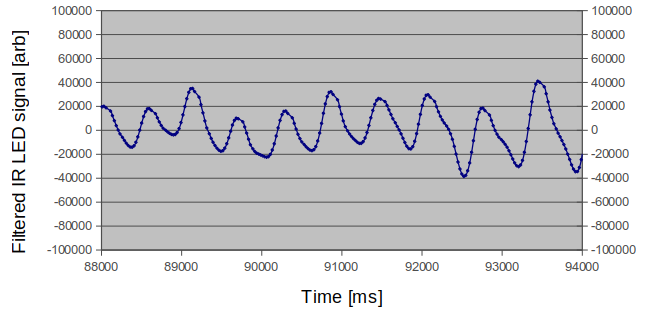 Finally, something that looks like a series of heartbeats
At last, something we can work with!
Importance of integer math
The native output of the sensor is an 18 bit unsigned integer. After removing the DC, I knew I would need a signed integer representation if I didn’t want to pull my hair out. In order for everything to run quickly, it is essential to avoid floats & doubles, so using signed 32 bit int32’s seemed like an ok compromise. Not as good as, say, limiting to 16bit unsigned, but still ok. I used a spreadsheet to check every point of each of the calculations to both ensure no overflow and also to use the full width of the int32 representation I did use.
Step 2 - detecting a beat
With the signal above, it is now reasonably straightforward to define when a beat occurs. My algorithm was:
- first find a minimum
- then ensure you get at least 6 data points increasing monotonically
- then find a maximum
- then ensure the maximum is > 0
- then ensure the (maximum-minimum) is within a (pretty liberal) range
And that constitutes a beat. It works really well, assuming the previous steps were followed. Here is a visualization of the beat detection algorithm in action on the signal above:
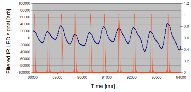 Like a metronome
You can also get sudden shifts in signal level, as the sensor shifts slightly during movement. The algorithm tracks that pretty well
 During a period when the signal level changed quickly
I also have periods of more erratic heartbeat, and the algorithm still performs well:
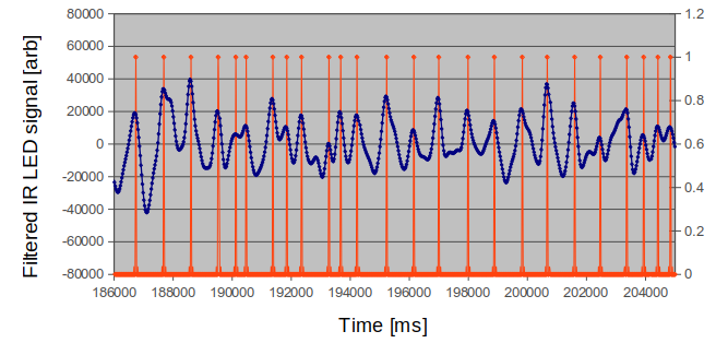 Following Mr. Crazy
Step 3 - Heartrate tracking
We’re close. All we need to do is keep track of the time between those beats & do a tiny bit of math to get heartrate. Its also a good idea to layer a bit of a tracking algorithm on top of this as well. To do that, I borrowed the heartbeat filter algorithm from my earlier heartrate monitor project. I made 3 changes:
- I tweaked it to run with fixed point math (fast!).
- I used a 50% “blanking time” in software to eliminate double beats or other hiccups.
- I used an actual timer to count time between beats
That algorithm already has 8s averaging built in. It worked even better than I expected. It even works replacing the IR channel with the red channel. Not quite as well, though, because of the weaker signal on the red channel. I’m really interested to try out green, but I need the MAX30101 for that. Maybe I’ll kill a weekend some time and build one up. Good news is that implementing the code should be fast - most of it is already written.
SPO2 algorithm
With all of this work done, getting the SPO2 measurement working was much simpler. All you need to do is once an (IR LED-based) beat is detected, keep track of the DC baseline from the DC filter and the maximum-minimum from the beat detector. Then also run the red LED signal through exactly the same algorithm, and extract the same two parameters. Then do the following math:
\[\begin{align*} R = \frac{AC_{red}}{AC_{IR}}\frac{DC_{IR}}{DC_{red}} \end{align*}\]where \(AC_{x}\) is the max-minimum of the filtered red and IR signals, and \(DC_{x}\) is the DC level of each signal that we strip with the DC blocking filter. We can finally apply the following mapping to get SPO2 %
\[\begin{align*} SpO2[\%] = 110-25R \end{align*}\]There are more complicated relationships between SpO2 and R you can use, but I started with this.
I did two more things to ensure SPO2 measurements were “good”:
- I did them during “stable periods” in my heartbeat - I only recorded measurements when the beat-to-beat variability is < 10%.
- I output the rolling average of 7 measurements.
RTOS & performance
So none of this would have been possible with using a real time operating system (RTOS). This was something I did not do on my OBD-II or MP3-player projects, and regretted it. I used one on my erg project and was happy with the result, so I invested a bunch of time getting it working here, and I love how things worked out. But I also learned a ton doing it, and the more I work on it, the more I realize how much more I need to learn. I’m sure I’ve made a zillion faux-pas (faux-pi?) in the implementation.
Since I was getting familiar with NilRTOS (aka Chibios/NIL) I continued on with it, with very minor tweaks to port from ATMega328 to ATMega1284. The system tick rate I chose was 64 us, as a compromise between responsivity and operating system overhead. I also am up to over 16 threads running concurrently - with minimal performance issues.
Chibios/RT and Chibios/NIL have both hardware (HAL) and OS (OSAL) abstraction layers built in. I am actually not using any of this capability (yet) in my code. But I will in some later version.
Threadsafeness
So to make something “threadsafe”, you have to anticipate that at any time, the thread (aka “task”) will be interrupted to let another higher priority thread/task. So non-RTOS-supported delays in the code are bad. It is also really important to keep critical sections really short, and to protect them if needed. I ended up making tweaks to many of the routines I had on hand, and I’m sure I did more harm than good to some of them.
How many threads/tasks?
Good question. I’m at 16 and counting. You really have to pay attention to priorities and ensure that the high priority ones “sleep” often enough to let the lower priority ones execute. Because Chibios/NIL is a fully pre-emptive OS, the second thing is that, on a per-thread-basis, you need to reserve stack space. This can get heavy if the thread has subroutines that call printf, for example. In fact, not paying attention to this causes all kinds of weird errors that can be traced to stack-trashing. If you’re still reading, I’m sure I’m not telling you anything you don’t already know.
Serial debugging
Essential for any embedded work. I have both a software and hardware UART implemented. I need to pick one and kill the other one at some point.
I2C, SPI and Serial buses - protecting
Besides multi-threaded operation, a second important RTOS capability is protecting precious resources. What the heck does that mean? It means that when all of the threads want to write to the LCD or serial port at the same time, you have to have a way to keep the peace. The answer is to use semaphores and mutexes. The version of Chibios/NIL that I used has a binary semaphore, and I implemented them for each of the following “multi-use” resources:
chSemObjectInit(&lcdUSE,1); //LCD
chSemObjectInit(&sdUSE,1); //SD Card
chSemObjectInit(&spiUSE,1); //SPI bus
chSemObjectInit(&i2cUSE,1); //I2C bus
chSemObjectInit(&usartUSE,1); //USART
chSemObjectInit(&ButtonPressed,1); //Button Handler
chSemObjectInit(&testTHREAD,1); // Test thread
Menus, icons and buttons
I had this grand vision of implementing the menu as icons instead of text. Still do. But I had already built up all of the code base around a text based menu and button navigation. I also had figured out how to make the button function depend on the context of the thread, using a third major capability of the RTOS: its ability to signal and pass messages between threads. So that’s what I did. The icon thing is on the list. This is going to be a multi-year project, so I’m buckled in.
SD cards and Fatfs-revisited
The SD card is great when you have limited memory, which of course is the case for these 8bit micros. Good for storing photos as backgrounds for the watch, and good as a destination for data logging. I was interested in both. Once again, Fatfs to the rescue. Implementing it didn’t take much time as I’d tackled it with a previous project. Using it with the RTOS is also working ok. I know my code is pretty amateurish, and I intend to come back to it at some point to do way better error checking/handling. I also think a queue might give better performance vs. using a semaphore to protect.
I also wanted to push the write speed performance. Initially, I saw about 15 ms delay per sample loop for an f_write() + f_sync() using unoptimized FatFS code, writing a 50+ byte message per loop to the file. The 20 ms delay seemed to be what others doing a similar thing see in their code, but I wanted to do much better. After studying the FatFS code, the trick was simply to aggregate data in a 512 byte buffer until it was filled, and then write just this 512 byte buffer to the SD card with a single f_write + f_sync. With a 32 byte message per sample, I only needed to do this write once every 16 samples, and the average performance penalty on this sample was only about 5 or 6 ms. So the performance rocked. And this can be further optimized since I am writing ascii characters, not binary data.
Bitmaps, fonts and shapes
Pushing bitmaps to the screen, supporting fonts and drawing things are all pieces of the lcd jiu-jitsu.
- I have a chunk of bitmap code that works well. Check.
- I have a base 5x7 font that can be scaled up and down in size. Check.
- I don’t have any of the lines and shapes tested yet. Coming soon with the compass app.
And about that printf
First of all, they warn you printf is not safe. Okay, well its my wrist, and there is no internet connection to this thing. Then they say printf is bloated code-wise. I can verify that first hand: RTOS threads need to reserve more than 1K of space to deal with it! Yikes! That’s more of a problem. So I’m about halfway through eliminating the avr-gcc printf and implementing xprintf instead. The only thing it doesn’t support is floats, but I’m working that. More to come.
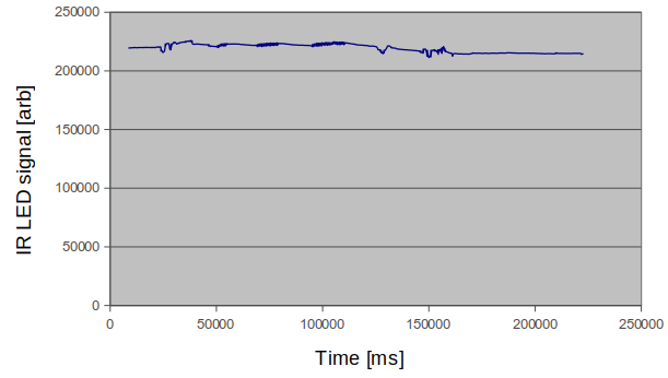
Low power design and analysis
One thing I did know was that the LCD can be a power hog. So I implemented a variable PWM backlight with a pushbutton and interrupt dedicated only to this. Other than that, I have to admit I didn’t really have a clue how long the battery was going to last. I didn’t even do the most basic benchtop measurements. You’ll see that understanding the power consumption was at the top of my list of things to work on. First data looks really promising:
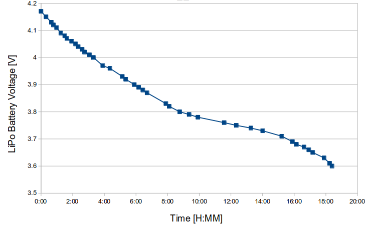 We’ll get 18 hours out of it
Pretty interesting how close this looks to published 1s LiPo discharge curves.
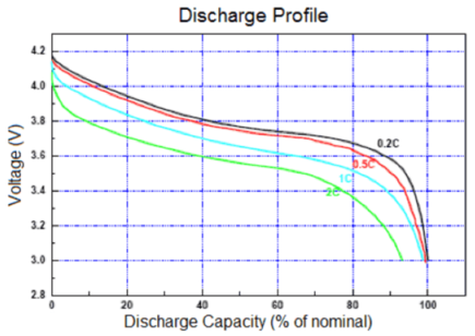 Typical LiPo discharging
Ours looks to be a discharge rate of about 0.05C. The battery is a 500 mAh battery, which implies an effective constant current consumption of 35mA. Seems high even with the LEDs on all the time, so I hope there is room to improve here. I’ll document more on this as results come in. Maybe this doesn’t need to be quite at the top of the “to do” list.
Debugging & Evaluating
In an application like this, there are a number of things to keep an eye on
- Voltage level of the battery - we just talked about it - which is done with the ADC and a bit of math
- Speed & timing performance of the RTOS - using its internal test thread
- Memory performance of the RTOS - especially status of each thread stack
- Individual thread real-time status: executing, blocked, stopped etc..
- Performance of the real-time clock - (I read the DS3231 status byte)
 Monitoring
Learning by re-doing
There are a zillion tweaks I already want to make to the software to both learn its limits and make it better. Right now, it ain’t really broke, so I won’t spend a ton of time fixing. But it is a nice platform on which to experiment and learn.
As far as new features, here’s my backlog, in order from “duh, you don’t have that yet?” to “probably will happen” to “ain’t gonna happen”:
- Low power consumption optimization
- Stopwatch/timer
- Way better screens and menu structure for almost everything
- Step counter
- Different variations on the outer skin
- Heartrate with green LED on MAX30101 instead of IR LED on MAX30102
- ICON-based UI instead of text menu
- Speaker/microphone support
- Wifi or bluetooth