
OBD2 4u
The journey of 1000 miles
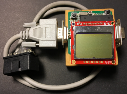 The finished build
Project overview
Have you ever seen that poster of the grizzly bear with the salmon in its mouth, subcaptioned “Sometimes the journey of 1000 miles ends very, very badly”? Well [spoiler alert], this is one of those journeys. The OBD2 interface (ISO-9141-2) that I spent about 10 months hacking - relatively successfully - is no longer really used in newer cars. So if you want to skip this one, feel free. Otherwise, I’ll take you on my journey to hack the car. A few things I wanted to see happen from the outset:
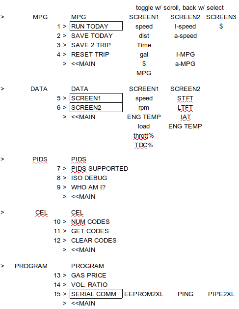
An easy-to-read display of the accumulated fuel costs while driving. Like this:
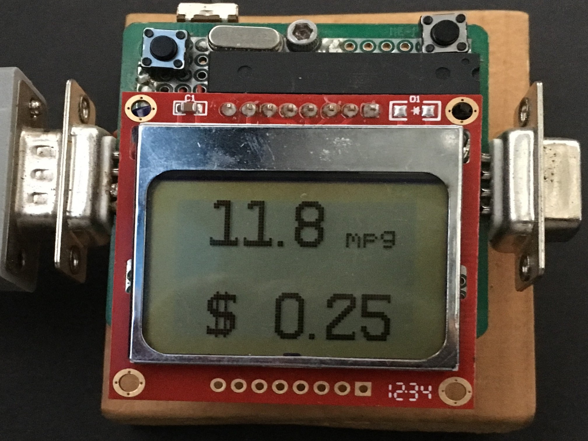 The only thing that really matters
Typical gas mileage for our car & minivan, including a sense of at what speed you get the optimum bang for your buck -
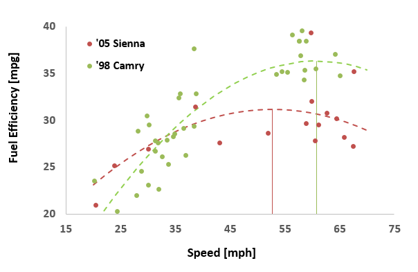 And the answer is: 61 miles/hr for the car & 53 miles/hr for the van
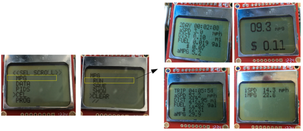
Some real-time output telemetry from the car while we were driving
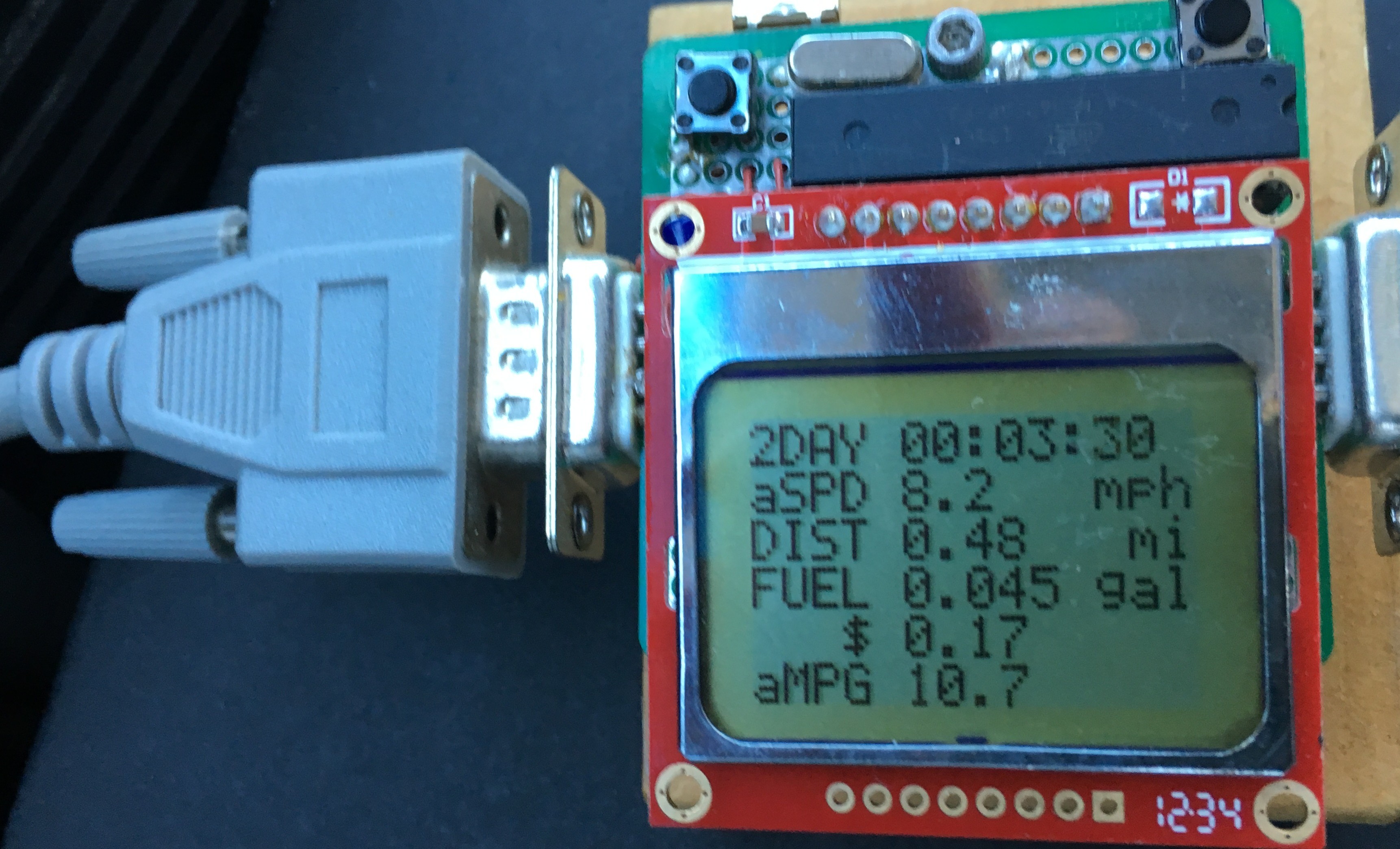 Give me the stats
And, of course, the check engine light (CEL or MIL) … and more to the point, my desire to figure out which code was causing it, & then douse it.
Here’s a video of this hack in action. As it always seems to be on my Camry, the code set was P0136, which is an oxygen sensor. I’ve been ignoring it for years. I’m sure that’s not good.
Here’s another video of the system booting up and me checking out the identity of the vehicle and what information I can see. My hands were freezing (it was -25C that day) & you gotta love the music that was playing on the radio-
For inspiration, there is some great information out there. In particular, I’d mention Bruce Lightner’s project: an AVR-based fuel consumption gauge. You can see it mentioned near the bottom of his homepage, among all the other great things referenced there. I’d also mention Trampas Stern’s very informative website. There are a few pieces of code - in particular the ISO timing protocols - that I used from his google code repository (which no longer looks to be available?). Both of these folks are awesome.
S.T.E.M.
Raw materials
A ‘98 Camry and ‘05 Sienna were what I had to work with. As I found out during this project, Toyota stayed close to the ISO-9141-2 specs on these vehicles, so I actually didn’t have a lot of problems “talking” to my cars once I actually understood the spec & the bugs were all flushed out (that took some time).
The basics - MAF, MAP, etc…
The fuel efficiency of an internal combustion engine can be estimated by … wait for it … chemistry. Knowing how much air is flowing into the engine, and knowing the ratio of air to fuel burned in the engine allows fuel consumption to be estimated. Some typical ratios are:
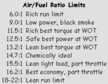 Fuel ratios .. I used 14.7:1 in the code
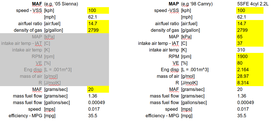
MAP stands for “manifold absolute pressure” and MAF stands for “mass air flow” - your car’s engine control unit will report one of these two. My ‘98 Camry only reports MAF and my ‘05 Sienna only reports MAP - go figure. Here’s the math to go from MAF to MPG.
MPG given a MAF value
\[\begin{align*} \text{MFF[g/s]} &= \frac{\text{MAF[g/s]} }{\text{AFR}}\\ \text{MFF[gallons/s]} &= \frac{\text{MFF[g/s]}}{\text{2799[g/gallon]} }\\ \text{MPG} &= \frac{\text{v[mph]/3600} } {\text{MFF[gallons/s]}} \tag{1} \label{MAF} \end{align*}\]where MFF is mass fuel flow, AFR is air-fuel ratio and 2799 g/gallon is the density of gasoline. If given a MAP value, first convert it to MAF,
MPG given a MAP value
\(\begin{align*} \text{MAF} = \frac{\text{RPM/60} * \text{MAP[kPa]} }{\text{(IAT[K]/2)} } * \text{VE[%]} * \\ \text{displacement[L]} * \frac{\text{28.97[g/mol]} }{\text{8.3[J/molK]} } \tag{2} \label{MAP} \end{align*}\)
& then use Equation \(\ref{MAF}\) above to get to MPG. Here is a little spreadsheet to get a feel for the numbers. In this example, most of the assumptions are relevant to highway cruising -
 A bunch of math gets me to what I want. And I want my MPG
Introduction to OBD2
OBD2 stands for “On Board Diagnostics” - it was introduced in 1996 & has gone through several iterations. It turns out, that the current protocol (based on the CAN bus protocol) was mandated for any automobile year ‘08 or later. Both of mine are earlier than ’08s, so they use the older protocol I needed to implement here. OK, that just means another project at some point.
OBD2 connector
Below is a picture of the OBD2 connector in my vehicles, the mating connector on my scanner, and the pinout of OBD2.
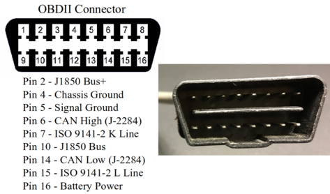 Connector & pinout
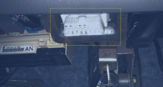 The mating plug on our minivan
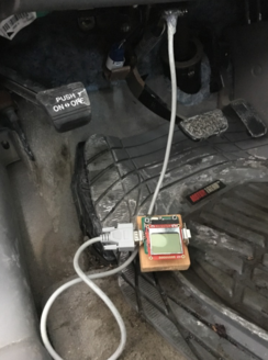 In place and connected
OBD2 protocols, timing and handshaking
OBD2 has several flavors - the variant I used is ISO-9141-2 which works with the Toyota spec. Another flavor (J1939) works with many older GM cars.
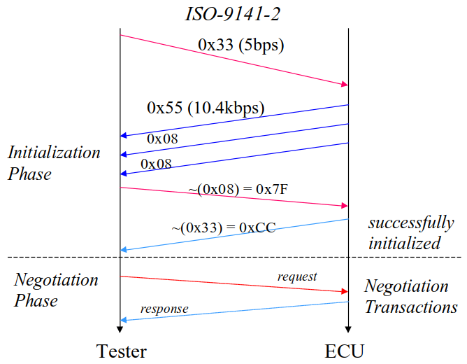
The initial “handshaking” has a timing process that looks like the following:
- Send 0x55 on K- & L- lines at 5 bits/sec (bps)
- Switch communications to 10400 bps
- Receive 0x08 0x08 at 10400 bps
- Send 0xF7 at 10400 bps
- Receive 0xCC at 10400 bps
 Initial communication protocol
Here is the initialization code:
void ISO_init_comm(uint8_t show) {
   lcd_clear();
   lcd_goto_xy(1,1);
   fprintf_P(&lcd_out, PSTR("INIT"));
// send 33, resp str should contain 55
	connect_put[0]=0x33;
//  switch_lcd_wait();
	iso_5baud_putc(connect_put[0]);
	for (i =0; i<3; i++)
	 {temp = iso_getb(&connect_get[i],1, ISO_W1_MAX*2);}
	connect_put[1] = ~connect_get[2];
	temp = iso_putb(&connect_put[1],1, ISO_W4_MIN);
	temp = iso_getb(&connect_get[3],1, ISO_W4_MAX*2);

	if(show ==1) {
		lcd_clear();
		lcd_goto_xy(1,1);
		fprintf_P(&lcd_out,PSTR("INIT"), connect_put[0]);
		lcd_goto_xy(1,2);
		fprintf_P(&lcd_out,PSTR("0x%x"), connect_put[0]);
		lcd_goto_xy(1,3);
		fprintf_P(&lcd_out,PSTR("%x..%x %x"), connect_get[0], connect_get[1], connect_get[2]);
		lcd_goto_xy(1,4);
		fprintf_P(&lcd_out,PSTR("%x..%x"), connect_put[1], connect_get[3]);
		clean_exit_partial();
	}
}
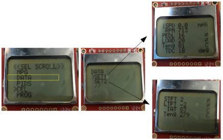
And here is a picture of how my software responds to the initialization
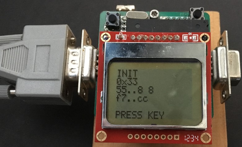 Oh Bee Dee, Oh Bee Dah, Life goes on, yeah!!! Got Hex 55, its alive
OBD2 PIDs (parameter IDs)
You can read about parameter IDs (PIDs) & diagnostic trouble codes (DTCs) in a number of places. Wikipedia has a list of many of the PIDs. The documentation is good, so I won’t regurgitate much of it here.
One interesting code to send, though, is
0x68 0x6A 0xF1 0x01 0x00 0xC4
This tells you which of the PID codes are actually readable on your particular vehicle. In the case of our Sienna, the response is:
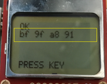 So what will Toyota actually give me access to????
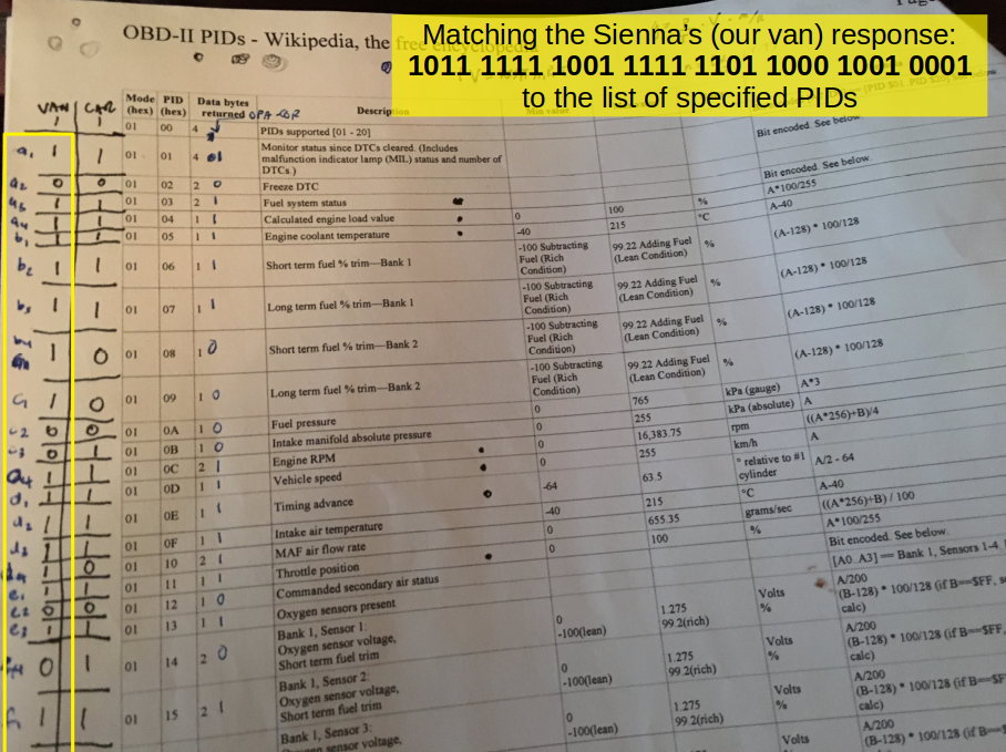
So it was these four hex bytes:
0xBF 0x9F 0xA8 0x91
What the heck does that mean? Well, we asked the van to respond to the code for Mode 01, PID 01. That’s what the two bold hex numbers are in the command we sent:0x68 0x6A 0xF1 0x01 0x00 0xC4. The response we should expect, based on the Wikipedia page is 4 Bytes A B C D (or 32 bits). For us A = 0xBF, B = 0x9F, C= 0xA8 and D = 0x91. The meaning of those bytes [A7 … D0] = [$PID $01 … PID $20] tells us whether that particular PID is implemented. So I first converted those 4 bytes to binary
0b 1011 1111 1001 1111 1101 1000 1001 0001
and then I matched them up to the Wikipedia list. I had previously done the same for our car, and you can see them both lined up on this cheat sheet:
 Now I know what we’re working with
In order to read the value of one of these PIDs that are available, you have to send the message in the format
0x68 0x6A 0xF1 0x[A] 0x[B] 0x[CSUM]
Where A = 01 for PID code set “mode 1” and B represents the actual code you want. CSUM represents a checksum, which is implemented like this:
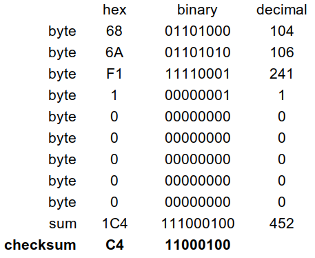 How to implement the CSUM checksum byte
The car’s ECU will send a message back in the format
0x48 0x6B 0x[ADDR] 0x41 0x[A] {optional:0x[B] 0x[C] 0x[D]} 0x[CSUM]
where A, B, C, D, etc.. are data bits you can do something with. Here is a screenshot of a little utility I wrote in Excel/VBA called “PING” that I could use from a laptop connected to my scanner. This allowed me to “explore” all of these different PIDs .. basically a hacking tool.
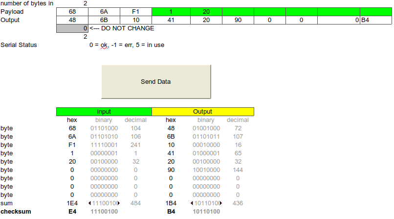 DIY hacking interface
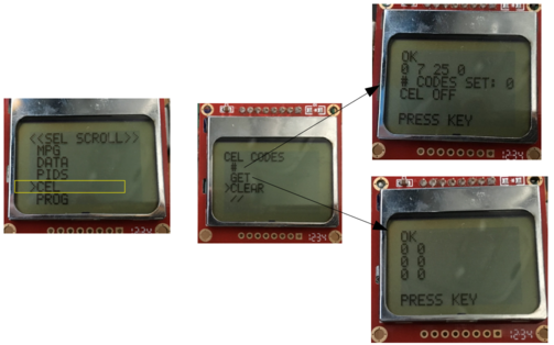
CEL codes
If your check engine light (CEL) - also known as the malfunction indicator lamp (MIL) - is on, you can see how many codes are set:
0x68 0x6A 0xF1 0x01 0x01 0xC5
Currently, I’m good:
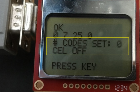 OK, so for once I’m on the right side of things with old MILlie-CELlie
In order to get CEL codes (also known as diagnostic trouble codes DTC), you need to send
0x68 0x6A 0xF1 0x03 0xC6
which gets you a response:
0x48 0x6B 0x[ADDR] 0x43 {repeated n times: 0x[A] 0x[B] 0x[C] 0x[D] 0x[E] 0x[F]} 0x[CSUM]
You can now interpret AB CD EF as diagnostic trouble codes. A typical response I get on my Camry is
A = 01, B = 36, C = 0, D = 0, E = 0, F = 0
… yes I (like you) almost always get P0136, the oxygen sensor code. Didn’t even need to build this thing - its always that same stupid code. Maybe I’ll do something about it next time.
 I’ll bet you 50 bucks its the dreaded “oxygen sensor” code
And of course, sending
0x68 0x6A 0xF1 0x04 0xC7
is magic, especially just prior to your annual safety check.
So, really, this entire setup is a communications protocol with the car. Lets dive into the hardware prior to coming back to some of the things you can do with it in software.
Hardware - circuit diagram
Below is a circuit diagram of the entire setup.
 Circuit diagram for OBD2 project–
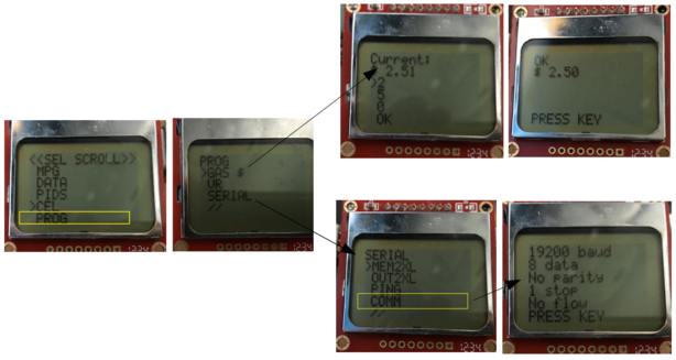
LCD & buttons
I used the Nokia 5110 LCD & driver plus a couple of pushbuttons to navigate around on the menu. Nothing really special there. More about the menu later.
Serial interface
I decided I might like to drive around and record what was happening on a laptop as I drove, among other things. So I put in a serial interface using a MAX232 chip. It requires a few capacitors and takes its input/output from the PD0/PD1 pins of the ATMega328. Also, in order to push up to 19200 baud and higher, you really have to start to pay attention to timing. There are some (really cool) software UARTs out there, but I didn’t use them on this project.
On the PC side, I used Excel to collect the information and also to ping the car. You may cringe, but VBA was a simple solution. I’ll add more documentation to this over time.
Circuit & package
Here are a few close ups of the circuit, front and back sides.
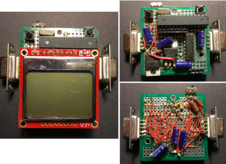 Front and back of circuit board
Not really much of a package to speak of. I just mounted the circuit board with a couple of standoffs to a piece of wood. I also put a bunch of shoe-goo around the connector once I had it completed - that stuff is solid.
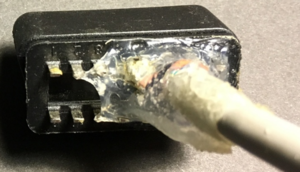 Keeping the OBD2 connector connected
L-line and K-line
The L-line is only needed for 1-direction (reader-to-car only), but the K-Line is a bidirectional line. I used separate ICs - the L9637 - for both of these lines. It is a line driver with a bunch of protection circuitry built in. All you need on the output lines is a 5K pullup to the battery voltage of 12V.
Testing, more testing, & finally success (0x55)
Once the hardware was built, I had to test it - and it was a bit of a pain running back and forth from the car every time I wanted to try something new. I got stuck for almost two weeks getting my car to say anything at all. I went through the hardware and software with a fine tooth comb, until I realized I had only connected the K-Line and not the L-line. It turns out, Toyota is looking for the L-Line as well for the initial communications.
At last, I got 0x55 in response to the pings. I was off and running now! 0x55 is a pattern 0b01010101, whose pattern adequately represents the ups and downs of those 2 weeks!
Software
It’s no badge of honor, but the size of code is 32kB, right at the limit of the Atmega328. Basically means I need to learn more compact coding skills. All of the code is posted at my repo.
Mother of all loops: polling v. interrupts
OK, so this is the project where I learned my lesson - but I implemented the code with one monster loop. It actually worked very well, except for one MAJOR problem that would really be a non-starter for anything PRO: the button-press recognition was all done by polling. This meant that sometimes it is unresponsive to a user’s button push, depending on the load of the processor. This happens rarely, but when it happens it is bad. The only real solution to this is to use an interrupts and an RTOS with a high priority handler thread for button presses, which I did on one of my future projects. In fact, it was exactly this problem that led me to investigate RTOS’s in the first place, but that’s another story. Learn by (re)doing.
Getting information from the car
A few more details associated with getting information from the car. Sometimes I knew exactly how the car would respond & and could send a compact request (in this case for the throttle position):
temp = iso_putb(&thrott_put[0],1, ISO_P3_MIN);
for (i =1; i<6; i++)
 {temp = iso_putb(&thrott_put[i],1, ISO_P4_MIN);}

temp = iso_getb(&thrott_get[0],1, ISO_P2_MAX*2);
for (i =1; i<7; i++)
{temp = iso_getb(&thrott_get[i],1, ISO_W2_MAX*2);}

serial_data = 0.3922*thrott_get[5];
In other cases, I did not know when the message would end, and would then have to compare the received byte with the running calculated checksum to determine the end of the message. (Yup, there’s a slight chance of making an error here, but we’re hacking folks).
ISO_init_comm(0);
temp = iso_putb(&ping_put[0],1, ISO_P3_MIN);
for (i =1; i<ping_length; i++) {
  temp = iso_putb(&ping_put[i],1, ISO_P4_MIN);
}
ping_length = 1;
temp = iso_getb(&ping_get[0],1, ISO_P2_MAX*2);
ping_sum = ping_get[0];
while(1) {
  temp = iso_getb(&ping_get[ping_length],1, ISO_W2_MAX*2);
  if ((ping_length>3) && (ping_get[ping_length] == (UBYTE) ping_sum)) {
    break; //checksum ... last bit
  } //end if
  ping_sum += ping_get[ping_length];
  ping_length++;
}//end while
You’ll notice in each function call to iso_putb and iso_getb there are variables like ISO_P3_MIN, ISO_P2_MAX_2, etc… These are timing windows for each of the commands and responses. The best explanation of this I’ve seen is Trampas Stern’s website - there are a couple of informative tables there. I’m sure there is official documentation somewhere on the dark web. These variables can be used to mask the timing windows and handle errors in the communication timings should they arise. I did very little error handling. Yes, I know - bad, bad, bad.
Averaging stuff
Most of the math here is very simple. You can see the formulas above for MPG. In some cases I wanted instantaneous values and in others I wanted running averages. For the running (time) averages like average speed, it was important to have a good master clock to always pick from to update & you just need to think about the definitions of averages.
running_time =(double) (running_time +dt_seconds);
MPG_temp = (double) (7.101*VSS_temp/MAF_temp);
running_dist =(double) (running_dist+0.6214*VSS_temp*dt_seconds/3600.0);
running_gallons =(double) (running_gallons+2.4307e-5*MAF_temp*dt_seconds);
MPG_ave = (double) (running_dist/running_gallons);
speed_ave = (double) (3600.0*running_dist/running_time);
I did everything with floating point math, so there were no issues there.
Menu implementation
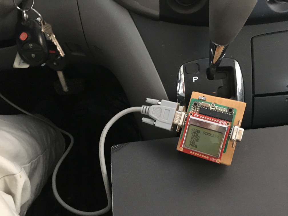 Powered-up & waiting for input
The menu was a simple 2D array that held elements for submenus. Each element of the array linked to a code block that I could execute. At any moment in time, the code keeps track of where the user has navigated to and uses a simple UI feature (a “>”) to give the user a visual cue. The interface is a 2-button implementation, with the left button navigating up and down, and the right button selecting. These buttons are context sensitive and do different things in the submenu.
In order not to get lost, I kept a little spreadsheet to remind me of the navigation path.
 Menu structure
And here are all of the different screens in their glory … yes, its quite a few.
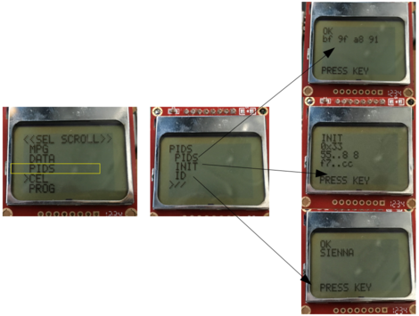
 OBD2 menu navigation
Below is the code to do the reset of the cursor position. Not sure this is the most efficient solution, but it worked for me.
while(1) {

      if (switch_is_pressed(&switchtype)) {
        if (switchtype == 1) { //we are scrolling
curItem++; // add one to curr item
        cursorCount++;
           if (menuitem[curMenu][curItem][0] == '\0') {
   curItem = 0;
   pageScroll = 0;
   cursorCount = 0;
   }
           if (cursorCount >= pageSize) {
            // we have scrolled past this page, go to next
            // remember, we check if we have scrolled off the MENU under clicks.  This is off the PAGE.
            pageScroll++;  // next "page"
            cursorCount=0; // reset cursor location
            }
            menuCount = pageScroll*pageSize;
  break;
        }

if (switchtype == 2) { //we are selecting
  // handle user input
  if (menuactn[curMenu][curItem]) {
    // has an action
    switch (menuactn[curMenu][curItem]) {
      case 1: //run MPG - DONE
        get_MPG();
        break;
      case 2: //screen 1 of data - DONE
        get_data_set1();
        break;
      case 3: //screen 2 of data - DONE
        get_data_set2();
        break;
      case 4: //PIDS supported - DONE
        get_supported_PIDs();
        break;
      // lots of other cases here
      case 999: //RETURN TO MAIN
        curMenu = 0; // return to main menu
        curItem = 0; // reset menu item to which cursor point
        pageScroll = 0; // reset menu page scroll
        cursorCount = 0; // reset menu location of page
        //menuCount = pageScroll*pageSize; // reprint from first line of this page
          break;
      }//switch
    menuCount = 0;
    break;
      }
    else //GO TO A SUB-MENU
    {
    curMenu = menulink[curMenu][curItem];  // set to menu selected by cursor
    curItem = 0; // reset menu item to which cursor point
    pageScroll = 0; // reset menu page scroll
    cursorCount = 0; // reset menu location of page
    menuCount = pageScroll*pageSize; // reprint from first line of this page
    break;
    }//end if action
    updateFlag = 1; // we have updated the menu.  Flag is used to delay user input
  } // end we are selecting
} // end switch is pressed
} // end while (1)
Settings & EEPROM
I decided to use the EEPROM to full effect in this project. Here is the layout of what I used it for:
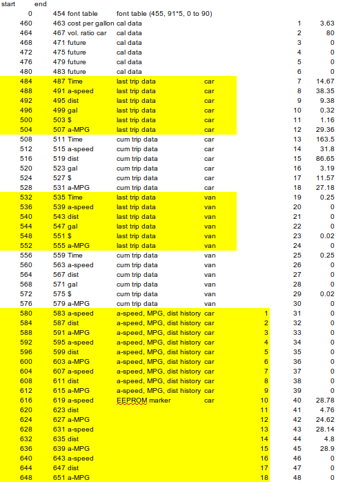 EEPROM layout
Mainly to hold averaged data that I could read out later (I did not implement any SD-card memory), plus a few of user-defined constants. There were a couple screens that allowed the user to change these constants. That was kind of a fun thing to implement with just the two pushbuttons available.
void set_gas_price (void){
_delay_ms(500);
lcd_clear();
eeprom_address = 460;
eeprom_read_block(&gas_price, (void*)eeprom_address, 4);
lcd_goto_xy(1,1);
fprintf_P(&lcd_out, PSTR("Current:"));
lcd_goto_xy(1,2);
fprintf_P(&lcd_out, PSTR("$%5.2f"), gas_price);

uint8_t d1=3;
uint8_t d2=5;
uint8_t d3=0;
uint8_t cur_item=3;
uint8_t done = 0;
while(1) {
if (done ==1) break;
lcd_goto_xy(1,3);
fprintf_P(&lcd_out, PSTR(" %d"), d1);
lcd_goto_xy(1,4);
fprintf_P(&lcd_out, PSTR(" %d"), d2);
lcd_goto_xy(1,5);
fprintf_P(&lcd_out, PSTR(" %d"), d3);
lcd_goto_xy(1,6);
fprintf_P(&lcd_out, PSTR(" OK"));

lcd_goto_xy(1,cur_item);
fprintf_P(&lcd_out, PSTR(">"));
_delay_ms(500);
while(1) {
if (switch_is_pressed(&switchtype)) {
 if (switchtype == 1) { //we are scrolling
 _delay_ms(500);
 cur_item++;
 if (cur_item == 7) cur_item = 3;
 break;
}  //switchtype1
 if (switchtype == 2) { //we incrementing
   _delay_ms(500);
  if (cur_item == 3) {
  d1++;
  if (d1==10) d1=0;
  }
  if (cur_item == 4) {
  d2++;
  if (d2 ==10) d2=0;
  }

  if (cur_item == 5) {
  d3++;
  if (d3 ==10) d3=0;
  }
  if (cur_item == 6) done =1;
  break;
  }//switchtype2
}//switchpressed
}//INNER WHILE

} //OUTER while
_delay_ms(500);
gas_price = (double)(100.0*d1+10.0*d2+d3)/100;
eeprom_address = 460;
eeprom_update_block(&gas_price, (void*)eeprom_address, 4);
lcd_clear();
clean_start();
eeprom_read_block(&gas_price, (void*)eeprom_address, 4);
fprintf_P(&lcd_out, PSTR("$%5.2f"), gas_price);
clean_exit_partial();
}
Talking to the PC
I used the built in USART to talk to the PC - the code on the microcontroller side has a few twists. The first trick was implementing the stream capability to minimize use the use of RAM by storing as much as possible in flash (program) memory - the chip has 32K of Flash but only 2K of RAM.
/********************************************************************************
Global Variables
********************************************************************************/
static FILE usart_out = FDEV_SETUP_STREAM(usart_putchar_printf, usart_getchar_printf, _FDEV_SETUP_RW);
static FILE lcd_out = FDEV_SETUP_STREAM(lcd_chr_printf, NULL, _FDEV_SETUP_WRITE);
Next, to talk to the PC over serial, I used Visual Basic for Applications (VBA) within Excel. It is flexible, and can usually do the job if you are in a hurry. I posted the spreadsheet with the code, and also broke out the module macros individually. I used a set of serial communications routines (Modcomm) written by David M. Hitchner, with two modifications:
-
Every system function declaration needs to add
PtrSafefor 64 bit operation'------------------------------------------------------------------------------- ' System Functions '------------------------------------------------------------------------------- Declare PtrSafe Sub AppSleep Lib "kernel32" Alias "Sleep" (ByVal dwMilliseconds As Long) -
I forced Commread to only return the number of bytes
lngSizethat were called so I could just read one byte at a time. This worked really well for the read rates I was using.'------------------------------------------------------------------------------- ' CommRead - Read serial port input buffer. ' ' Parameters: ' intPortID - Port ID used when port was opened. ' strData - Data buffer. ' lngSize - Maximum number of bytes to be read. ' ' Returns: ' Error Code - 0 = No Error. '------------------------------------------------------------------------------- If udtCommStat.cbInQue > 0 Then 'If udtCommStat.cbInQue > lngSize Then ' lngRdSize = udtCommStat.cbInQue 'Else lngRdSize = lngSize 'End If Else lngRdSize = 0 End If
So there are 4 macros I wrote that work over serial to a PC: PIPE2XL, PIPE2XL2, EEPROM2XL and PING.
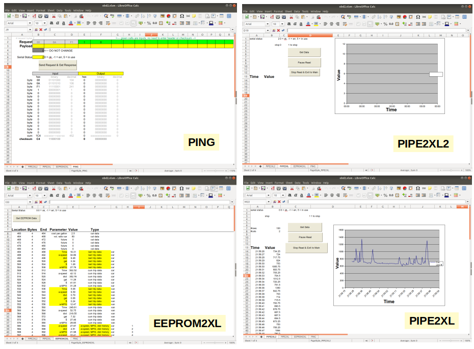 Clickety clack … Cartalk
EEPROM2XL allowed me to read the EEPROM at any point in time, which was useful since I saved data there. PING - the hacker tool - was already described above, and could be used to send arbitrary commands to the car to see how it responded. Here it is again in action:
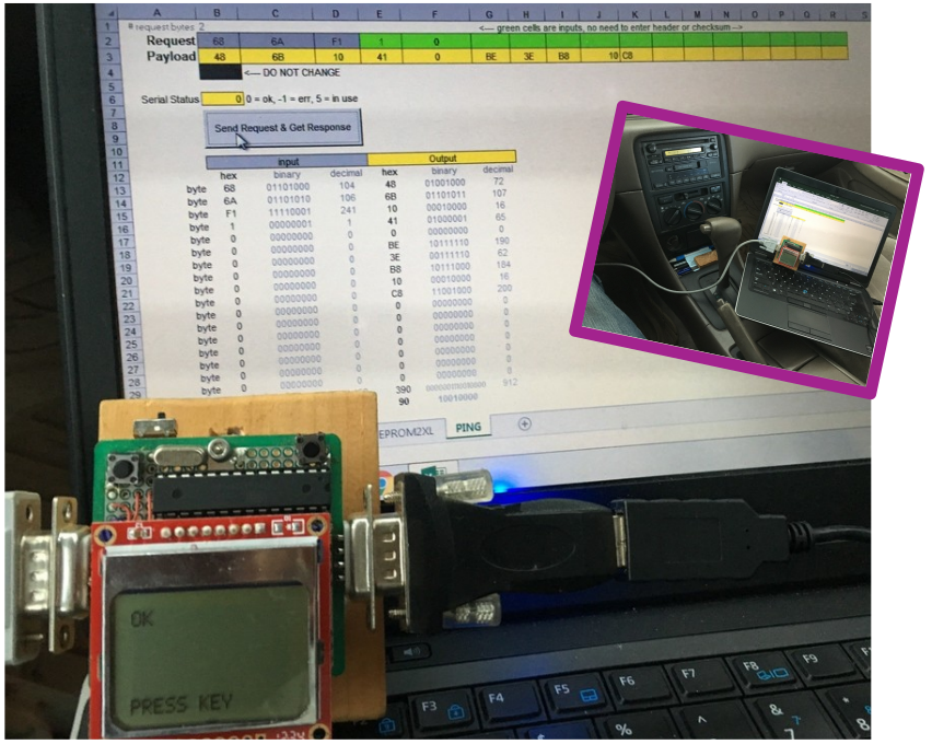 PING … doing its thing
PIPE2XL and PIPE2XL2 allowed me to ask the car to stream real-time data. Here is a video of the RPMs streaming to a laptop:
& here is an example of my speed on a road near our house ending in a traffic light, check back as I’ll try to post some cooler stuff.
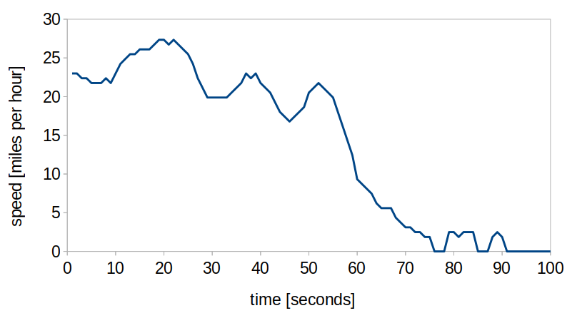 Kinda boring … but analyzing a bunch of these might be interesting
All of them used the same VBA code snippet to ensure receiving good data from the microcontroller
Do While (still_going = 1)
  end_of_string = 0
  buf = ""
    Do While (end_of_string = 0) 'not yet end of string
        'read one byte at a time into a buffer
         strData = ""
         Do While (strData = "") 'nothing in buffer
              lngStatus = CommRead(intPortID, strData, 1)
         Loop 'nothing in buffer
         If ((strData <> Chr(13)) And (strData <> Chr(10))) Then
              buf = buf + strData
         Else
             If strData = Chr(10) Then 'we read the string, flush buffer
                  Call CommFlush(intPortID)
                  end_of_string = 1
              End If
         End If
    Loop 'end of string
    total_count = total_count + 1
    response_count = response_count + 1
    If Val(buf) = 999 Then
        still_going = 0
    Else
        Worksheets("PING").Cells(j + 2, response_count + 1).Value = Hex(Val(buf))
    End If
Loop 'still_going
In the microcontroller, I escaped each byte with \r\n
fprintf_P(&usart_out,PSTR("%08.2f\r\n"), serial_data);
and in this particular case I also finish the overall transmission with 999 to make the VBA serial link end cleanly
fprintf_P(&usart_out,PSTR("%06d\r\n"),999);
Learning by re-doing
CAN bus
I actually got a bunch of use out of this project, and will probably make a CAN version at some point. If I do, I’ll probably go for an RTOS and design it so it can be mounted and unmounted in the car. Will have to start to go hunting for all of the CAN specs and protocols.